PCC, the configuration of the distribution system and
relevant impedances must be known.
A commonly used term for describing the impedance of a
grid is the short circuit ratio R
sce
, defined as the ratio
between the short circuit apparent power of the supply at
the PCC (S
sc
) and the rated apparent power of the load
(S
equ
).
R
sce
=
S
ce
S
equ
where
S
sc
=
U
2
Z
supply
and
S
equ
=
U
×
I
equ
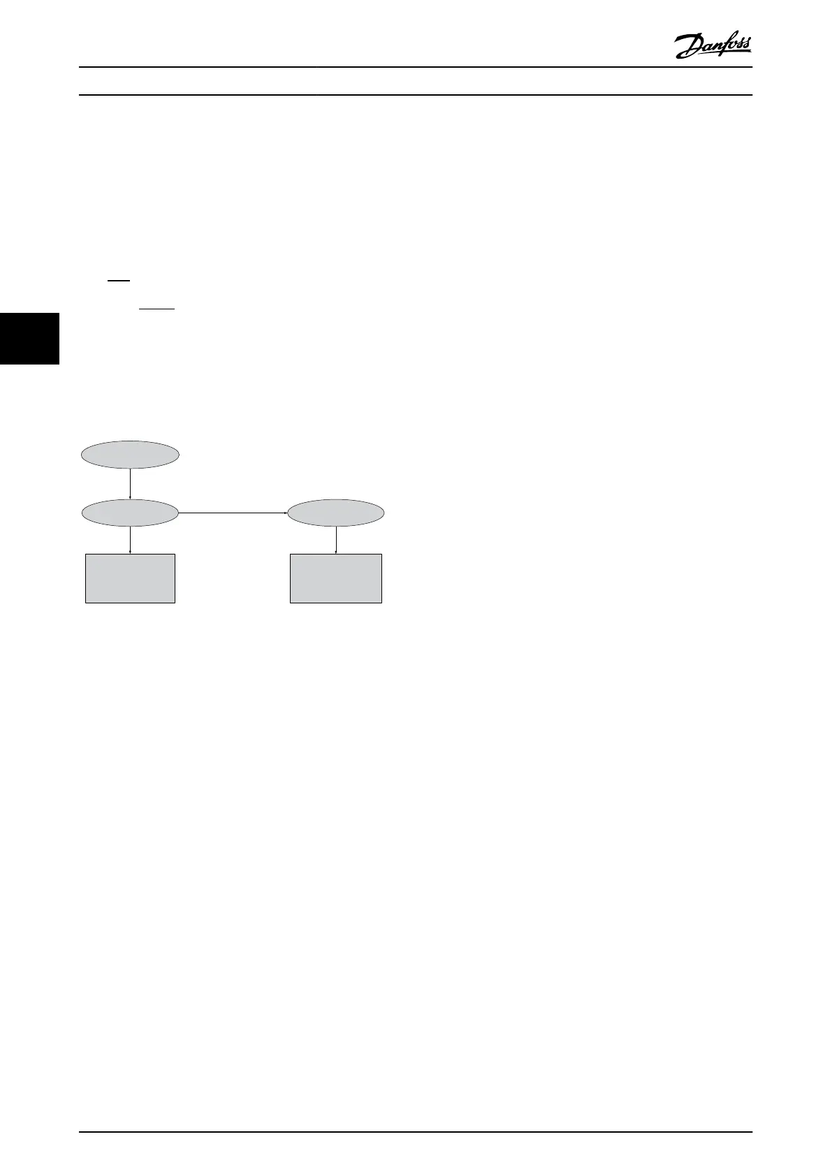
The negative effect of harmonics is 2-fold
•
Harmonic currents contribute to system losses (in
cabling, transformer)
•
Harmonic voltage distortion causes disturbance
to other loads and increase losses in other loads
Non-linear
Current Voltage
System
Impedance
Disturbance to
other users
Contribution to
system losses
130BB541.10
Illustration 5.6 Negative Effects of Harmonics
5.3.2 Harmonic Limitation Standards and
Requirements
The requirements for harmonic limitation can be
•
application specific requirements
•
standards that must be observed
The application specific requirements are related to a
specific installation where there are technical reasons for
limiting the harmonics.
Example
A 250 kVA transformer with 2 110 kW motors connected is
sufficient, if one of the motors is connected directly on-line
and the other is supplied through a frequency converter.
However, the transformer is undersized, if both motors are
frequency converter supplied. Using additional means of
harmonic reduction within the installation or selecting low
harmonic drive variants makes it possible for both motors
to run with frequency converters.
There are various harmonic mitigation standards,
regulations and recommendations. Different standards
apply in different geographical areas and industries. The
following standards are the most common:
•
IEC61000-3-2
•
IEC61000-3-12
•
IEC61000-3-4
•
IEEE 519
•
G5/4
See the AHF 005/010 Design Guide for specific details on
each standard.
In Europe, the maximum THVD is 8% if the plant is
connected via the public grid. If the plant has its own
transformer, the limit is 10% THVD. The VLT
®
AutomationDrive is designed to withstand 10% THVD.
5.3.3
Harmonic Mitigation
In cases where additional harmonic suppression is
required, Danfoss offers a wide range of mitigation
equipment. These are:
•
12-pulse drives
•
AHF filters
•
Low Harmonic Drives
•
Active Filters
The choice of the right solution depends on several
factors:
•
The grid (background distortion, mains
unbalance, resonance and type of supply
(transformer/generator)
•
Application (load profile, number of loads and
load size)
•
Local/national requirements/regulations (IEEE519,
IEC, G5/4, etc.)
•
Total cost of ownership (initial cost, efficiency,
maintenance, etc.)
Always consider harmonic mitigation if the transformer
load has a non-linear contribution of 40% or more.
5.3.4
Harmonic Calculation
Danfoss offers tools for calculation of harmonics, see
chapter 9.6.5 PC Software.
5.4
Galvanic Isolation (PELV)
5.4.1 PELV - Protective Extra Low Voltage
PELV offers protection by way of extra low voltage.
Protection against electric shock is ensured when the
electrical supply is of the PELV type and the installation is
made as described in local/national regulations on PELV
supplies.
System Integration
VLT
®
AutomationDrive FC 301/FC 302 Design Guide, 0.25-75 kW
54 MG33BF02 - Rev. 2013-12-20
55

 Loading...


