130BA186.11
P 3-03
P 3-02
Sum of all
references
P 3-00 Reference Range= [0] Min to Max
Resulting reference
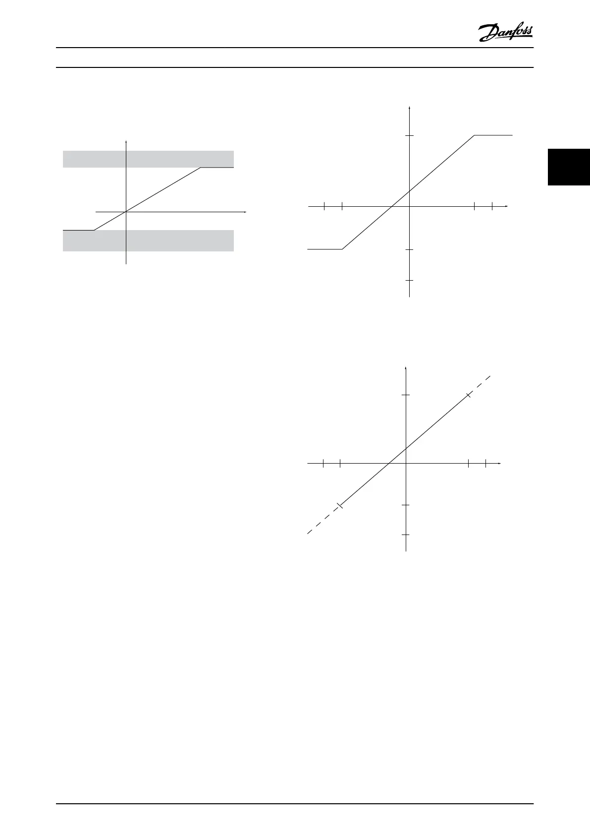
Illustration 3.16 Sum of all References with 1-00 Configuration
Mode set to [3] Process
3.7.3
Scaling of Preset References and Bus
References
Preset references are scaled according to the following
rules:
•
When 3-00 Reference Range: [0] Min - Max 0%
reference equals 0 [unit] where unit can be any
unit e.g. RPM, m/s, bar etc. 100% reference equals
the Max (abs (3-03 Maximum Reference), abs
(3-02 Minimum Reference)).
•
When 3-00 Reference Range: [1] -Max - +Max 0%
reference equals 0 [unit] -100% reference equals -
Max Reference 100% reference equals Max
Reference.
Bus references are scaled according to the following
rules:
•
When 3-00 Reference Range: [0] Min - Max. To
obtain max resolution on the bus reference the
scaling on the bus is: 0% reference equals Min
Reference and 100% reference equals Max
reference.
•
When 3-00 Reference Range: [1] -Max - +Max
-100% reference equals -Max Reference 100%
reference equals Max Reference.
3.7.4
Scaling of Analog and Pulse
References and Feedback
References and feedback are scaled from analog and pulse
inputs in the same way. The only difference is that a
reference above or below the specified minimum and
maximum “endpoints” (P1 and P2 in Illustration 3.17) are
clamped, whereas a feedback above or below is not.
(RPM)
Resource output
Resource
input
Terminal X low
Terminal X
high
Low reference/feedback value
High reference/feedback
value
130BA181.10
-1500
-6 8 (V)
1500
-10 10
P1
P2
0
-600
Illustration 3.17 Scaling of Analog and Pulse References and
Feedback
(RPM)
Resource output
Resource
input
Terminal X low
Terminal X
high
Low reference/feedback value
High reference/feedback
value
130BA182.10
-1500
-6 8 (V)
1500
-10 10
P1
P2
0
-600
Illustration 3.18 Scaling of Reference Output
3.7.5
Dead Band Around Zero
In some cases, the reference (in rare cases also the
feedback) should have a dead band around zero (i.e. to
make sure the machine is stopped when the reference is
“near zero”).
To activate the dead band and to set the amount of
dead band, set the following:
•
Either Minimum Reference Value or Maximum
Reference Value must be zero. In other words;
Either P1 or P2 must be on the X-axis in
Illustration 3.19.
•
And both points defining the scaling graph are in
the same quadrant.
Basic Operating Principles
VLT
®
AutomationDrive FC 301/FC 302 Design Guide, 0.25-75 kW
MG33BF02 - Rev. 2013-12-20 31
3 3

 Loading...


