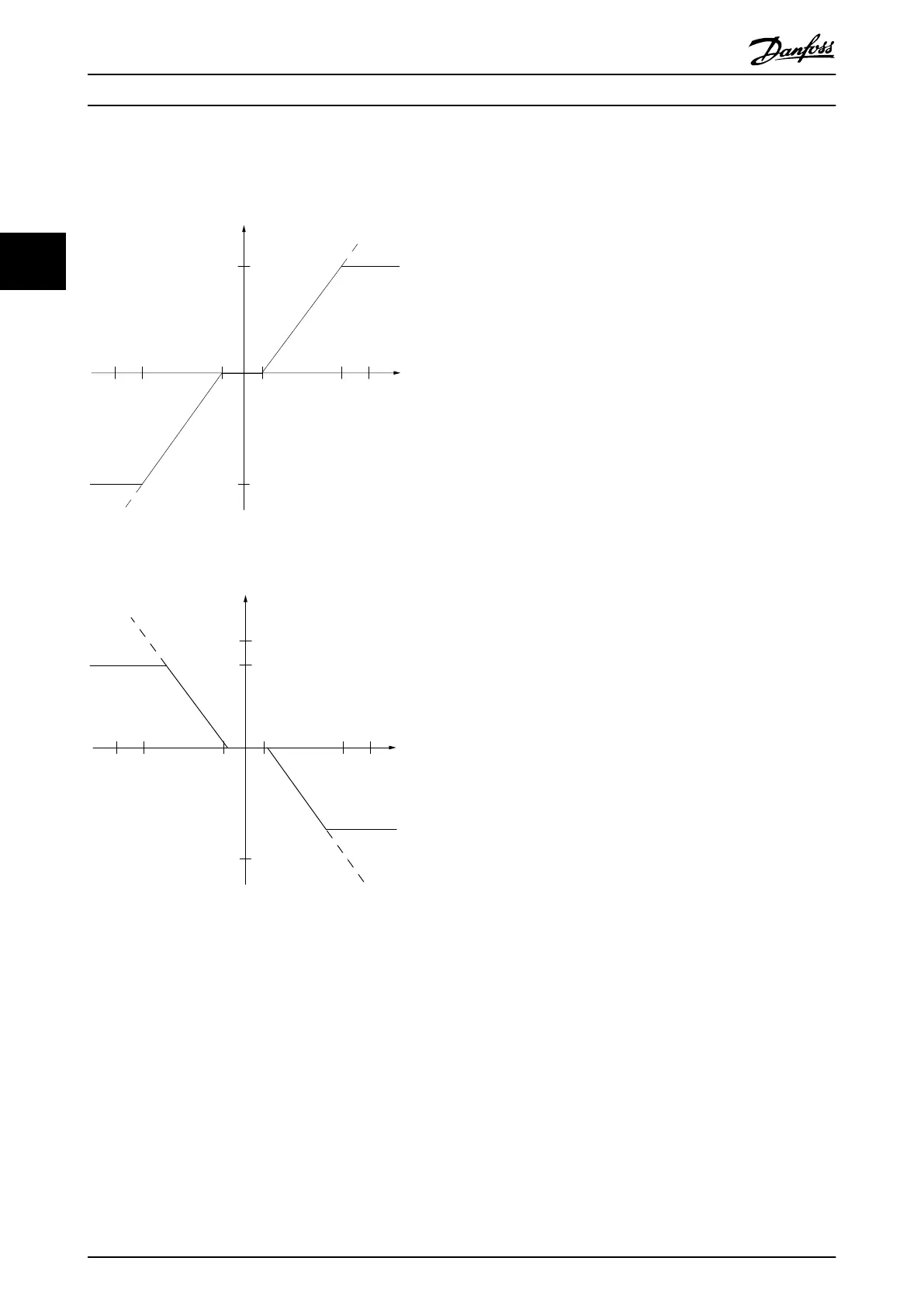
The size of the dead band is defined by either P1 or P2 as
shown in Illustration 3.19.
(RPM)
Resource output
Resource
input
Quadrant 2
Quadrant 3
Quadrant 1
Quadrant 4
Terminal X
low
Terminal X
high
Low reference/feedback
value
High reference/feedback
value
-1 1
130BA179.10
-1500
-6 6
(V)
1500
-10 10
P1
P2
0
Illustration 3.19 Dead Band
(RPM)
Resource output
Resource
input
Quadrant 2
Quadrant 3
Quadrant 1
Quadrant 4
Terminal X
low
Terminal X
high
Low reference/feedback
value
High reference/feedback
value
-1 1
130BA180.10
-1500
-6 6
(V)
1500
-10 10
P1
P2
0
Illustration 3.20 Reverse Dead Band
Thus a reference endpoint of P1 = (0 V, 0 RPM) does not
result in any dead band, but a reference endpoint of e.g.
P1 = (1 V, 0 RPM) results in a -1 V to +1 V dead band in
this case provided that the end point P2 is placed in either
Quadrant 1 or Quadrant 4.
Basic Operating Principles
VLT
®
AutomationDrive FC 301/FC 302 Design Guide, 0.25-75 kW
32 MG33BF02 - Rev. 2013-12-20
33

 Loading...


