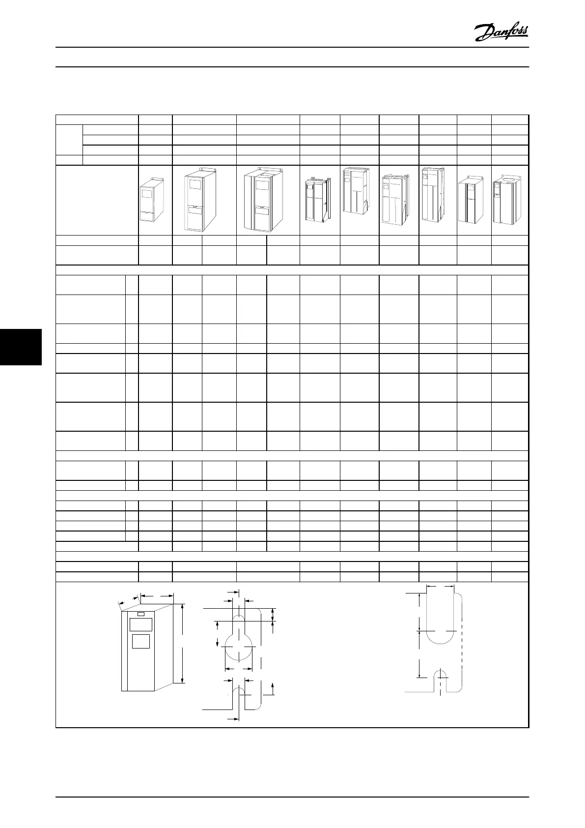
8.2 Mechanical Dimensions
Enclosure Type A1 A2 A3 A4 A5 B1 B2 B3 B4
Power
[kW]
200-240 V 0.25–1.5 0.25-2.2 3-3.7 0.25-2.2 0.25-3.7 5.5-7.5 11 5.5-7.5 11-15
380-480/500 V 0.37-1.5 0.37-4.0 5.5-7.5 0.37-4 0.37-7.5 11-15 18.5-22 11-15 18.5-30
525-600 V 0.75-7.5 0.75-7.5 11-15 18.5-22 11-15 18.5-30
525-690 V 1.1-7.5 11-22 11-30
Illustrations
IP 20 20 21 20 21 55/66 55/66 21/55/66 21/55/66 20 20
NEMA Chassis Chassis Type 1 Chassis Type 1 Type
12/4X
Type
12/4X
Type
1/12/4X
Type
1/12/4X
Chassis Chassis
Height [mm]
Height of back
plate
A 200 268 375 268 375 390 420 480 650 399 520
Height with de-
coupling plate for
Fieldbus cables
A 316 374 - 374 - - - - - 420 595
Distance between
mounting holes
a 190 257 350 257 350 401 402 454 624 380 495
Width [mm]
Width of back
plate
B 75 90 90 130 130 200 242 242 242 165 230
Width of back
plate with one C
option
B - 130 130 170 170 - 242 242 242 205 230
Width of back
plate with 2 C
options
B - 150 150 190 190 - 242 242 242 225 230
Distance between
mounting holes
b 60 70 70 110 110 171 215 210 210 140 200
Depth [mm]
Depth without
option A/B
C 207 205 207 205 207 175 200 260 260 249 242
With option A/B C 222 220 222 220 222 175 200 260 260 262 242
Screw holes [mm]
c 6.0 8.0 8.0 8.0 8.0 8.25 8.25 12 12 8 -
d ø8 ø11 ø11 ø11 ø11 ø12 ø12 ø19 ø19 12 -
e ø5 ø5.5 ø5.5 ø5.5 ø5.5 ø6.5 ø6.5 ø9 ø9 6.8 8.5
f 5 9 9 6.5 6.5 6 9 9 9 7.9 15
Max weight [kg]
2.7 4.9 5.3 6.6 7.0 9.7 13.5/14.2 23 27 12 23.5
Front cover tightening torque [Nm]
Plastic cover (low IP) Click Click Click - - Click Click Click Click
Metal cover (IP55/66) - - - 1.5 1.5 2.2 2.2 - -
Illustration 8.1 Top and Bottom Mounting Holes
(B4, C3 and C4 only)
Table 8.1 Mechanical Dimensions, Enclosure Types A and B
Mechanical Installation
VLT
®
AutomationDrive FC 301/FC 302 Design Guide, 0.25-75 kW
108 MG33BF02 - Rev. 2013-12-20
88
 Loading...


