3.6.3
Control Structure in VVC
+
+
_
+
_
Cong. mode
Ref.
Process
P 1-00
High
+f max.
Low
-f max.
P 4-11
Motor speed
low limit (RPM)
P 4-12
Motor speed
low limit (Hz)
P 4-13
Motor speed
high limit (RPM)
P 4-14
Motor speed
high limit (Hz)
Motor
controller
Ramp
Speed
PID
P 7-20 Process feedback
1 source
P 7-22 Process feedback
2 source
P 7-00 Speed PID
feedback source
P 1-00
Cong. mode
P 4-19
Max. output freq.
-f max.
Motor
controller
P 4-19
Max. output freq.
+f max.
P 3-**
P 7-0*
130BA055.10
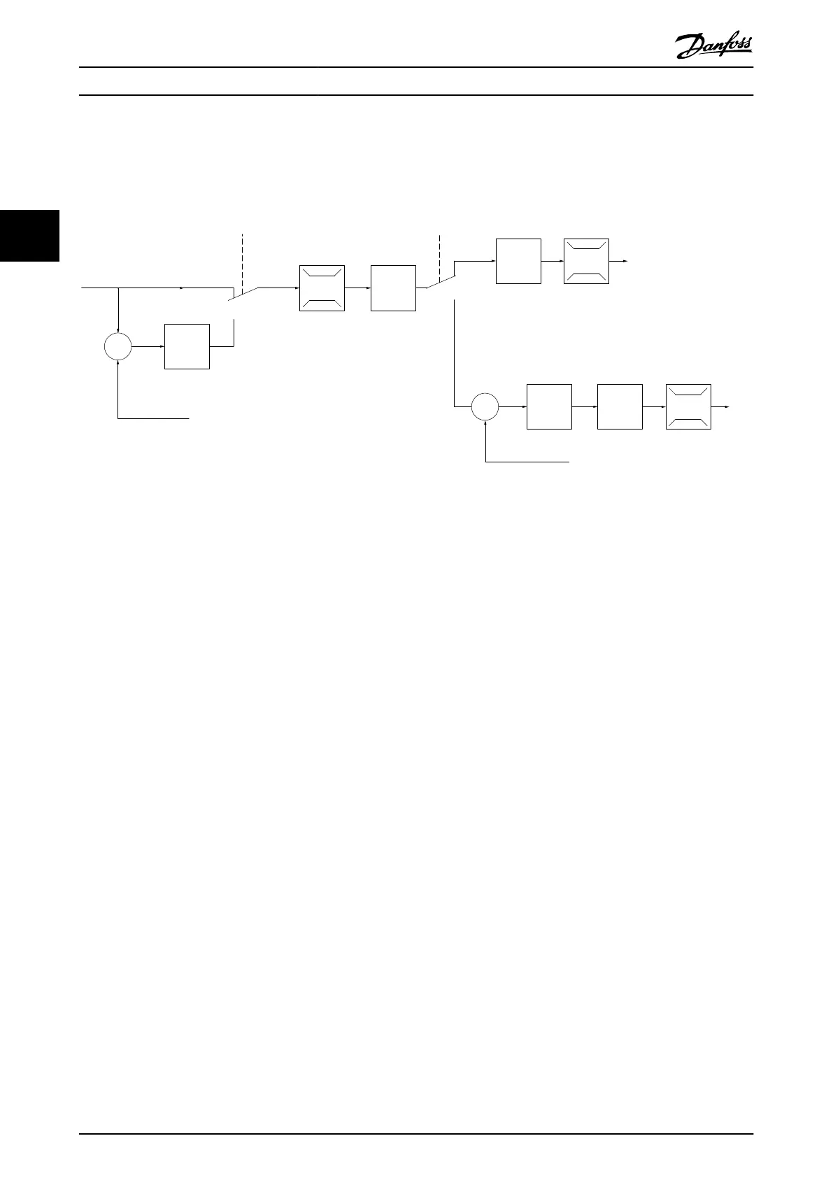
Illustration 3.6 Control Structure in VVC
+
Open Loop and Closed Loop Configurations
See Active/Inactive Parameters in Different Drive Control Modes in the Programming Guide for an overview of which control
configuration is available, depending on selection of AC motor or PM Non salient motor. In the configuration shown in
Illustration 3.6, 1-01 Motor Control Principle is set to [1] VVC
+
and 1-00 Configuration Mode is set to [0] Speed open loop. The
resulting reference from the reference handling system is received and fed through the ramp limitation and speed limitation
before being sent to the motor control. The output of the motor control is then limited by the maximum frequency limit.
If 1-00 Configuration Mode is set to [1] Speed closed loop, the resulting reference is passed from the ramp limitation and
speed limitation into a speed PID control. The Speed PID control parameters are located in parameter group 7-0* Speed PID
Ctrl. The resulting reference from the Speed PID control is sent to the motor control limited by the frequency limit.
Select [3] Process in 1-00 Configuration Mode to use the process PID control for closed loop control of e.g. speed or pressure
in the controlled application. The Process PID parameters are located in parameter group 7-2* Process Ctrl. Feedb and 7-3*
Process PID Ctrl.
Basic Operating Principles
VLT
®
AutomationDrive FC 301/FC 302 Design Guide, 0.25-75 kW
20 MG33BF02 - Rev. 2013-12-20
33

 Loading...


