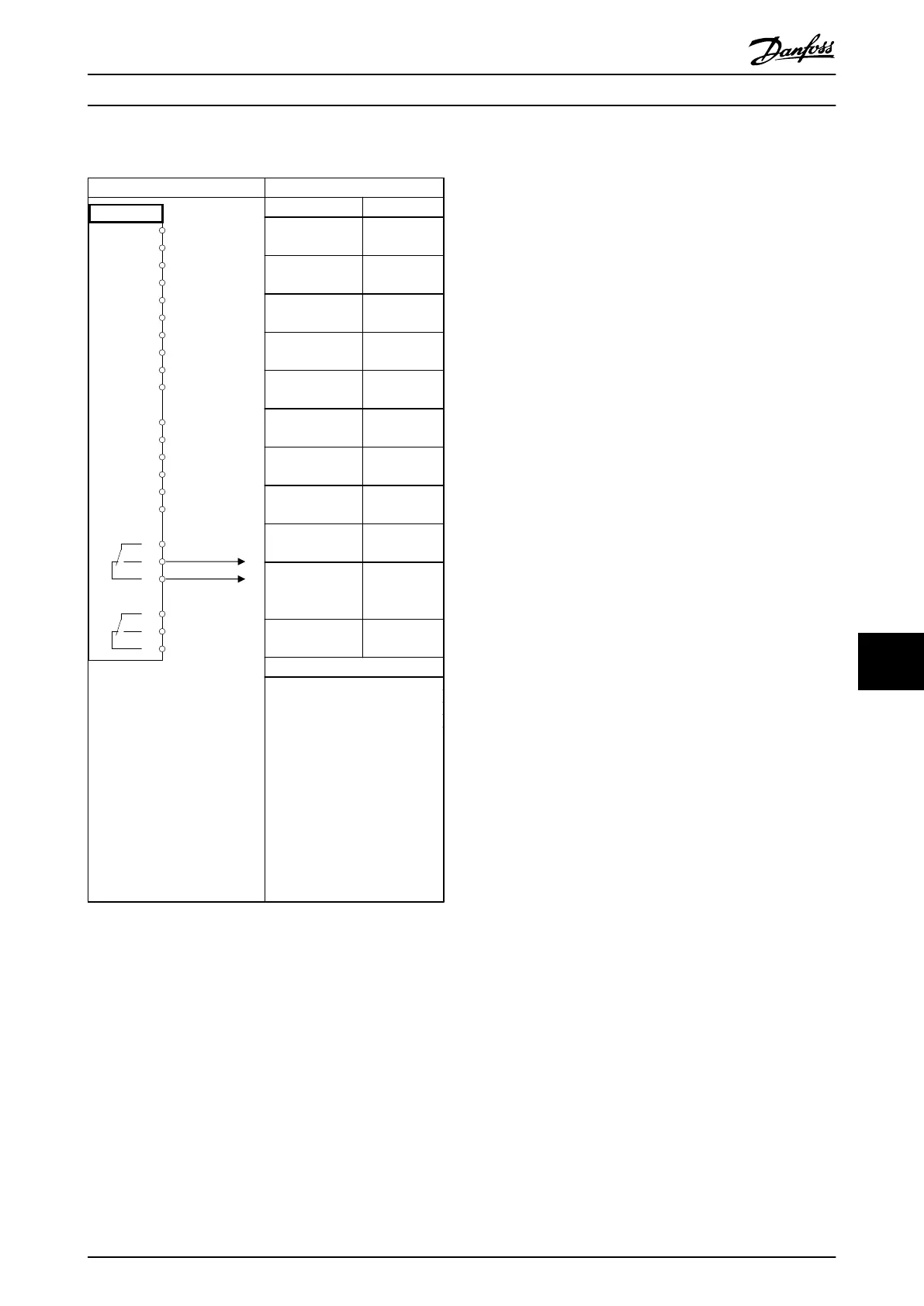
Application Example
Parameters
FC
+24 V
+24 V
D IN
D IN
D IN
COM
D IN
D IN
D IN
D IN
+10 V
A IN
A IN
COM
A OUT
COM
R1R2
12
13
18
19
20
27
29
32
33
37
50
53
54
55
42
39
01
02
03
04
05
06
130BB839.10
Function Setting
7-00 Speed PID
Feedback Source
[2] MCB 102
17-11 Resolution
(PPR)
1024*
13-00 SL
Controller Mode
[1] On
13-01 Start
Event
[19] Warning
13-02 Stop
Event
[44] Reset
key
13-10 Comparat
or Operand
[21] Warning
no.
13-11 Comparat
or Operator
[1] ≈*
13-12 Comparat
or Value
90
13-51 SL
Controller Event
[22]
Comparator 0
13-52 SL
Controller Action
[32] Set
digital out A
low
5-40 Function
Relay
[80] SL digital
output A
* = Default Value
Notes/comments:
Warning 90 will be issued when
the feedback signal from the
encoder does not correspond
to the reference. The SLC
monitors Warning 90 and in
the case that Warning 90
becomes TRUE then Relay 1 is
triggered.
External equipment may then
indicate that service may be
required.
Table 10.15 Using SLC to Set a Relay
Application Examples
VLT
®
AutomationDrive FC 301/FC 302 Design Guide, 0.25-75 kW
MG33BF02 - Rev. 2013-12-20 151
10 10

 Loading...


