11.2.8.1 Electrical and Mechanical Specifications
Analogue Input
Number of analogue inputs 1
Format 0–20 mA or 4–20 mA
Wires 2
Input impedance <200 Ω
Sample rate 1 kHz
3rd order filter 100 Hz at 3 dB
The option is able to supply the analogue sensor with 24 V
DC (terminal 1).
Temperature Sensor Input
Number of analogue inputs supporting PT100/1000 3
Signal type PT100/1000
Connection PT 100 2 or 3 wire/PT1000 2 or 3 wire
Frequency PT100 and PT1000 input 1 Hz for each channel
Resolution 10 bit
Temperature range
-50–204 °C
-58–399 °F
Galvanic Isolation
The sensors to be connected are expected to be galvanically isolated from the mains voltage
level IEC 61800-5-1 and UL508C
Cabling
Maximum signal cable length 500 m
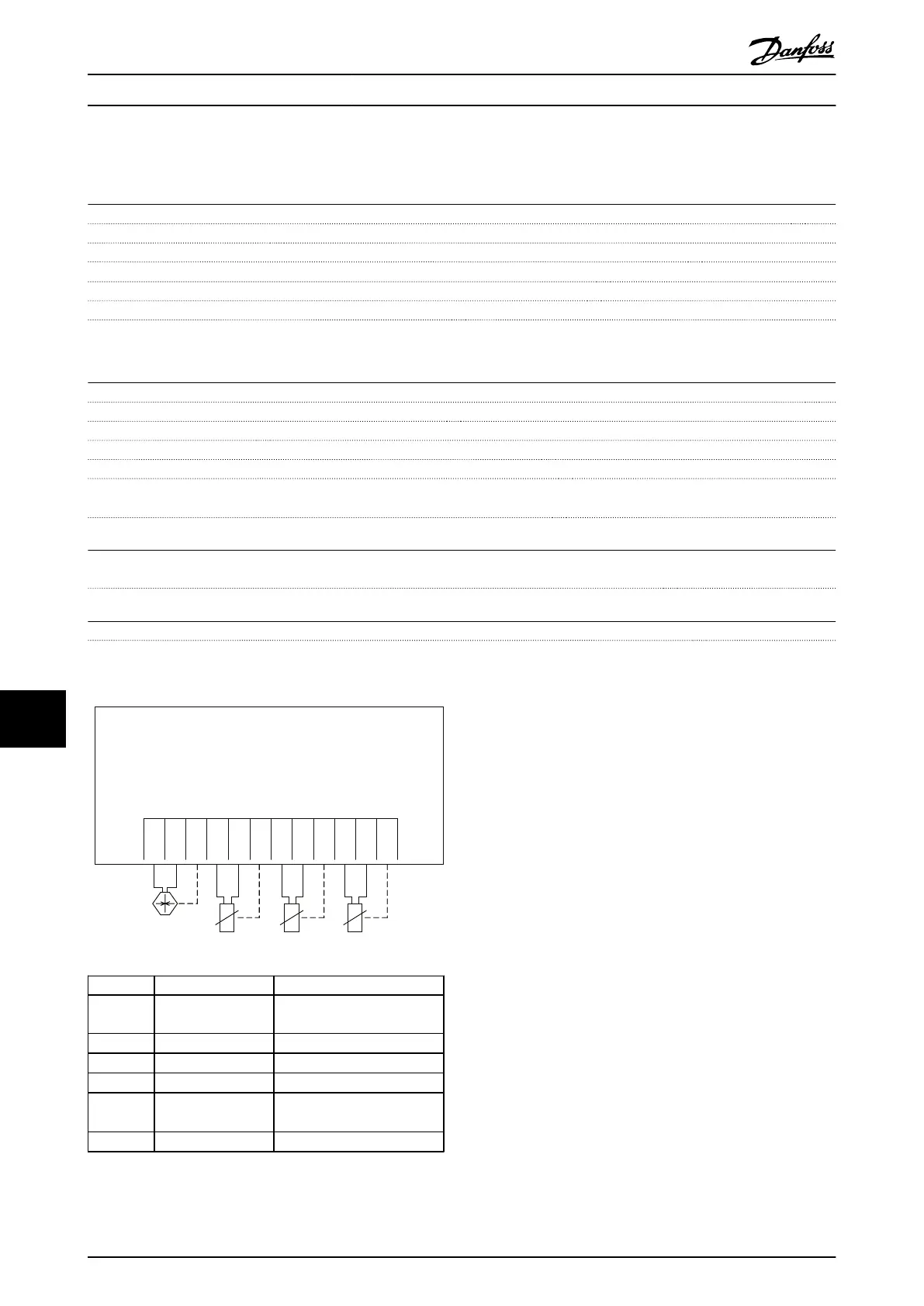
11.2.8.2 Electrical Wiring
MCB 114
Sensor Input Option B
SW. ver. xx.xx Code No. 130B1272
4-20mA
2 or 3
wire
2 or 3
wire
2 or 3
wire
2 or 3
wire
130BB326.10
Terminal Name Function
1 VDD 24 V DC to supply 4-20 mA
sensor
2 I in 4-20 mA input
3 GND Analog input GND
4, 7, 10 Temp 1, 2, 3 Temperature input
5, 8, 11 Wire 1, 2, 3
3
rd
wire input if 3 wire
sensors are used
6, 9, 12 GND Temp. input GND
Illustration 11.18 MCB 114
Options and Accessories
VLT
®
AutomationDrive FC 301/FC 302 Design Guide, 0.25-75 kW
164 MG33BF02 - Rev. 2013-12-20
1111

 Loading...


