T
ta
tc
tb
to ta
tc
tb
to ta
130BA167.10
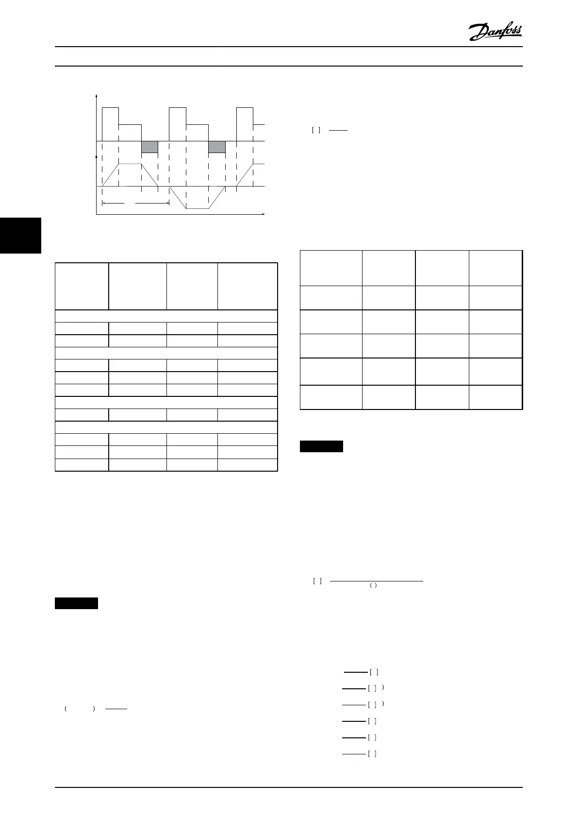
Load
Time
Speed
Illustration 5.8 Typical Braking Cycle
Cycle time (s)
Braking duty
cycle at
100% torque
Braking duty
cycle at over
torque
(150/160%)
200-240 V
PK25-P11K 120 Continuous 40%
P15K-P37K 300 10% 10%
380-500 V
PK37-P75K 120 Continuous 40%
P90K-P160 600 Continuous 10%
P200-P800 600 40% 10%
525-600 V
PK75-P75K 120 Continuous 40%
525-690 V
P37K-P400 600 40% 10%
P500-P560 600
40%
1)
10%
2)
P630-P1M0 600 40% 10%
Table 5.9 Braking at High Overload Torque Level
1) 500 kW at 86% braking torque/560 kW at 76% braking torque
2) 500 kW at 130% braking torque/560 kW at 115% braking torque
Danfoss offers brake resistors with duty cycle of 5%, 10%
and 40%. If a 10% duty cycle is applied, the brake resistors
are able to absorb brake power for 10% of the cycle time.
The remaining 90% of the cycle time is used on dissipating
excess heat.
NOTICE
Make sure the resistor is designed to handle the
required braking time.
The max. permissible load on the brake resistor is stated as
a peak power at a given intermittent duty cycle and can
be calculated as:
ED
dutycycle
=
tb
T
cycle
where tb is the braking time in seconds and T cycle is the
total cycle time.
The brake resistance is calculated as shown:
R
br
Ω =
U
dc
2
P
peak
where
P
peak
= P
motor
x M
br
[%] x η
motor
x η
VLT
[W]
The brake resistance depends on the intermediate circuit
voltage (U
dc
).
The FC 301 and FC 302 brake function is settled in 4 areas
of mains.
Size
Brake active Warning
before cut
out
Cut out
(trip)
FC 301/FC 302
200-240 V
390 V 405 V 410 V
FC 301 380-480
V
778 V 810 V 820 V
FC 302 380-500
V
810 V 840 V 850 V
FC 302 525-600
V
943 V 965 V 975 V
FC 302 525-690
V
1084 V 1109 V 1130 V
Table 5.10 Brake Limits [UDC]
NOTICE
Check that the brake resistor can cope with a voltage of
410 V, 820 V, 850 V, 975 V or 1130 V - unless Danfoss
brake resistors are used.
Danfoss recommends the brake resistance R
rec
, i.e. one that
guarantees that the frequency converter is able to brake at
the highest braking torque (M
br(%)
) of 160%. The formula
can be written as:
R
rec
Ω =
U
dc
2
x
100
P
motor
x
M
br
%
x
η
VLT
x
η
motor
η
motor
is typically at 0.90
η
VLT
is typically at 0.98
For 200 V, 480 V, 500 V and 600 V frequency converters,
R
rec
at 160% braking torque is written as:
200
V
:
R
rec
=
107780
P
motor
Ω
480
V
:
R
rec
=
375300
P
motor
Ω
1
480
V
:
R
rec
=
428914
P
motor
Ω
2
500
V
:
R
rec
=
464923
P
motor
Ω
600
V
:
R
rec
=
630137
P
motor
Ω
690
V
:
R
rec
=
832664
P
motor
Ω
System Integration
VLT
®
AutomationDrive FC 301/FC 302 Design Guide, 0.25-75 kW
56 MG33BF02 - Rev. 2013-12-20
55
 Loading...


