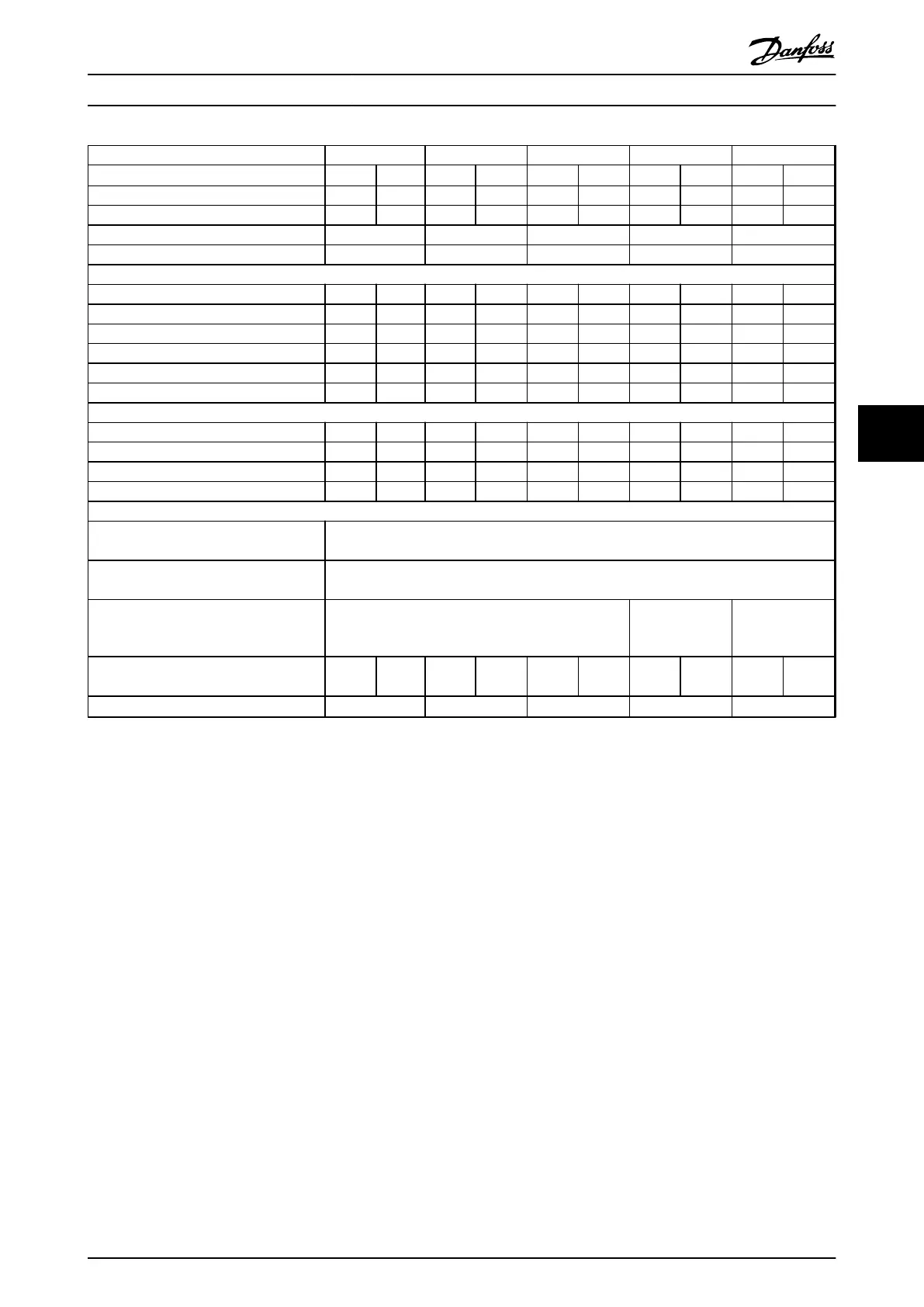
Type Designation P30K P37K P45K P55K P75K
High/Normal Overload
1)
HO NO HO NO HO NO HO NO HO NO
Typical Shaft output at 550 V (kW) 22 30 30 37 37 45 45 55 50 75
Typical Shaft output at 690 V [kW] 30 37 37 45 45 55 55 75 75 90
Enclosure IP20 B4 C3 C3 D3h D3h
Enclosure IP21, IP55 C2 C2 C2 C2 C2
Output current
Continuous (525-550V) [A] 36.0 43.0 43.0 54.0 54.0 65.0 65.0 87.0 87.0 105
Intermittent (60 s overload) (525-550V) [A] 54.0 47.3 64.5 59.4 81.0 71.5 97.5 95.7 130.5 115.5
Continuous (551-690V) [A] 34.0 41.0 41.0 52.0 52.0 62.0 62.0 83.0 83.0 100
Intermittent (60 s overload) (551-690V) [A] 51.0 45.1 61.5 57.2 78.0 68.2 93.0 91.3 124.5 110
continuous KVA (at 550 V) [KVA] 34.3 41.0 41.0 51.4 51.4 61.9 61.9 82.9 82.9 100
continuous KVA (at 690 V) [KVA] 40.6 49.0 49.0 62.1 62.1 74.1 74.1 99.2 99.2 119.5
Max. input current
Continuous (at 550 V) [A] 36.0 49.0 49.0 59.0 59.0 71.0 71.0 87.0 87.0 99.0
Intermittent (60 s overload) (at 550 V) [A] 54.0 53.9 72.0 64.9 87.0 78.1 105.0 95.7 129 108.9
Continuous (at 690 V) [A] 36.0 48.0 48.0 58.0 58.0 70.0 70.0 86.0 - -
Intermittent (60 s overload) (at 690 V) [A] 54.0 52.8 72.0 63.8 87.0 77.0 105 94.6 - -
Additional specifications
Max. cable-cross section for mains and
motor [mm
2
] ([AWG])
150 (300 MCM)
Max. cable cross-section for load share and
brake [mm
2
] ([AWG])
95 (3/0)
Max cable cross-section
4)
for mains
disconnect [mm
2
] ([AWG])
95, 70, 70
(3/0, 2/0, 2/0)
185, 150, 120
(350 MCM, 300
MCM, 4/0)
-
Estimated power loss
at rated max. load [W]
3)
600 740 740 900 900 1100 1100 1500 1500 1800
Efficiency
2)
0,98
0,98 0,98 0,98 0,98
Table 6.12 B4, C2, C3 Enclosure, Mains Supply 525-690 V IP20/IP21/IP55 - Chassis/NEMA1/NEMA 12 (FC 302 only), P30K-P75K
For fuse ratings, see chapter 9.3.1 Fuses and Circuit Breakers.
1)
High overload=150% or 160% torque during 60 s. Normal overload=110% torque during 60 s.
2)
Measured using 5 m screened motor cables at rated load and rated frequency.
3)
The typical power loss is at nominal load conditions and expected to be within
±
15% (tolerance relates to variety in voltage and
cable conditions).
Values are based on a typical motor efficiency (eff2/eff3 border line). Motors with lower efficiency also add to the power loss in the
frequency converter and opposite.
If the switching frequency is increased compared to the default setting, the power losses may rise significantly.
LCP and typical control card power consumptions are included. Further options and customer load may add up to 30 W to the losses.
(Though typical only 4 W extra for a fully loaded control card, or options for slot A or slot B, each).
Although measurements are made with state of the art equipment, some measurement inaccuracy must be allowed for (
±
5%).
4)
The 3 values for the max. cable cross section are for single core, flexible wire and flexible wire with sleeve, respectively.
Product Specifications
VLT
®
AutomationDrive FC 301/FC 302 Design Guide, 0.25-75 kW
MG33BF02 - Rev. 2013-12-20 67
6 6
 Loading...


