Safe stop Terminal 37
3, 4)
(Terminal 37 is fixed PNP logic)
Voltage level 0-24 V DC
Voltage level, logic'0' PNP <4 V DC
Voltage level, logic'1' PNP >20 V DC
Maximum voltage on input 28 V DC
Typical input current at 24 V 50 mA rms
Typical input current at 20 V 60 mA rms
Input capacitance 400 nF
All digital inputs are galvanically isolated from the supply voltage (PELV) and other high-voltage terminals.
1) Terminals 27 and 29 can also be programmed as output.
2) Except safe stop input Terminal 37.
3) See VLT
®
Frequency Converters - Safe Torque Off Operating Instructions for further information about terminal 37 and Safe
Stop.
4) When using a contactor with a DC coil inside in combination with Safe Stop, it is important to make a return way for the
current from the coil when turning it off. This can be done by using a freewheel diode (or, alternatively, a 30 or 50 V MOV for
quicker response time) across the coil. Typical contactors can be bought with this diode.
Analog inputs
Number of analog inputs 2
Terminal number 53, 54
Modes Voltage or current
Mode select Switch S201 and switch S202
Voltage mode Switch S201/switch S202 = OFF (U)
Voltage level -10 to +10 V (scaleable)
Input resistance, R
i
approx. 10 kΩ
Max. voltage ± 20 V
Current mode Switch S201/switch S202 = ON (I)
Current level 0/4 to 20 mA (scaleable)
Input resistance, R
i
approx. 200 Ω
Max. current 30 mA
Resolution for analog inputs 10 bit (+ sign)
Accuracy of analog inputs Max. error 0.5% of full scale
Bandwidth 100 Hz
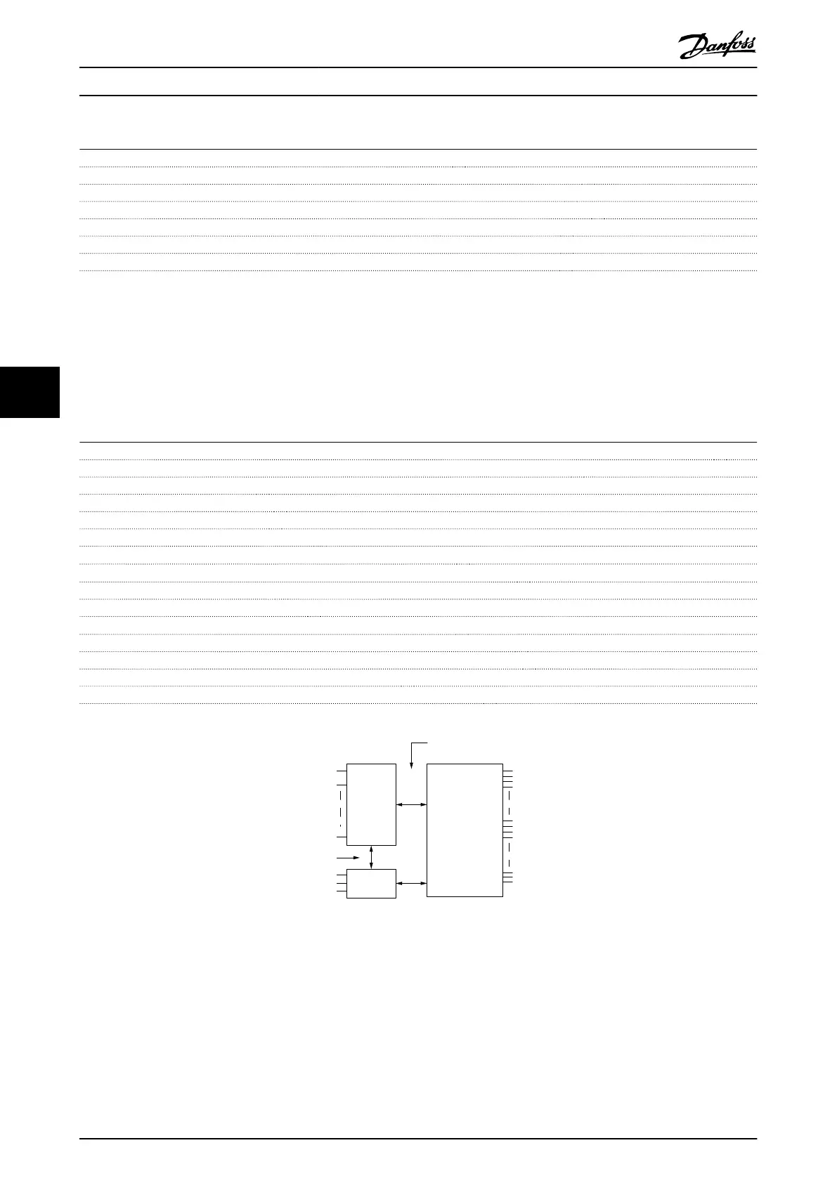
The analog inputs are galvanically isolated from the supply voltage (PELV) and other high-voltage terminals.
Mains
Functional
isolation
PELV isolation
Motor
DC-Bus
High
voltage
Control
+24V
RS485
18
37
130BA117.10
Illustration 6.1 PELV Isolation
Product Specifications
VLT
®
AutomationDrive FC 301/FC 302 Design Guide, 0.25-75 kW
70 MG33BF02 - Rev. 2013-12-20
66

 Loading...


