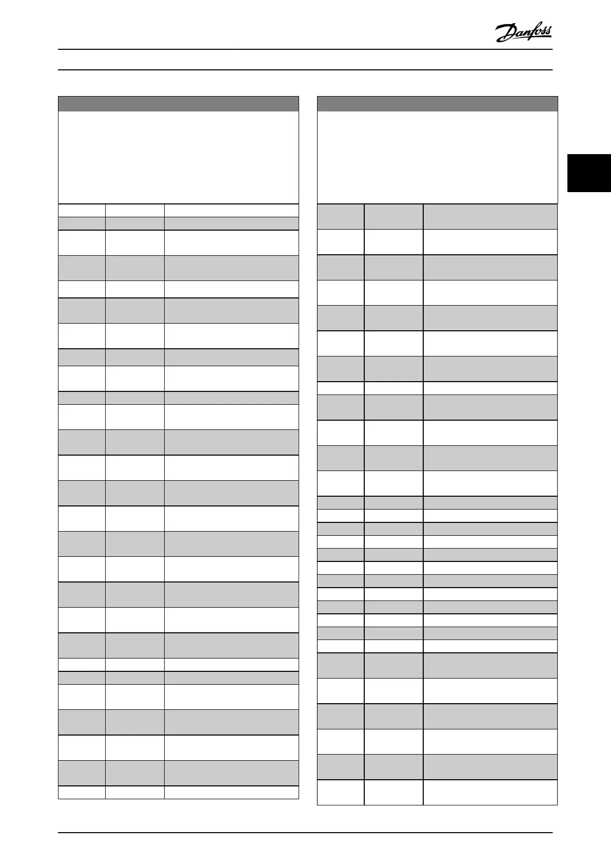
5-40 Function Relay
Array [8]
(Relay 1 [0], Relay 2 [1]
Option MCB 105: Relay 7 [6], Relay 8 [7] and Relay 9 [8]).
Select options to dene the function of the relays.
The selection of each mechanical relay is realized in an array
parameter.
Option: Function:
[1] Control Ready
[2] Drive ready
[3] Drive rdy/rem
ctrl
[4] Standby / no
warning
[5] Running Default setting for relay 2.
[6] Running / no
warning
[8] Run on ref/no
warn
[9] Alarm Default setting for relay 1.
[10] Alarm or
warning
[11] At torque limit
[12] Out of current
range
[13] Below current,
low
[14] Above current,
high
[15] Out of speed
range
[16] Below speed,
low
[17] Above speed,
high
[18] Out of feedb.
range
[19] Below
feedback, low
[20] Above
feedback, high
[21] Thermal
warning
[25] Reverse
[26] Bus OK
[27] Torque limit &
stop
[28] Brake, no
brake war
[29] Brake ready,
no fault
[30] Brake fault
(IGBT)
[31] Relay 123
5-40 Function Relay
Array [8]
(Relay 1 [0], Relay 2 [1]
Option MCB 105: Relay 7 [6], Relay 8 [7] and Relay 9 [8]).
Select options to dene the function of the relays.
The selection of each mechanical relay is realized in an array
parameter.
Option: Function:
[33] Safe stop
active
[35] External
Interlock
[36] Control word
bit 11
[37] Control word
bit 12
[40] Out of ref
range
[41] Below
reference, low
[42] Above ref,
high
[45] Bus ctrl.
[46] Bus ctrl, 1 if
timeout
[47] Bus ctrl, 0 if
timeout
[51] MCO
controlled
[59] Remote,enable
,no TW
[60] Comparator 0
[61] Comparator 1
[62] Comparator 2
[63] Comparator 3
[64] Comparator 4
[65] Comparator 5
[70] Logic rule 0
[71] Logic rule 1
[72] Logic rule 2
[73] Logic rule 3
[74] Logic rule 4
[75] Logic rule 5
[80] SL digital
output A
[81] SL digital
output B
[82] SL digital
output C
[83] SL digital
output D
[84] SL digital
output E
[85] SL digital
output F
Parameter Descriptions Programming Guide
M0010001 Danfoss A/S © 10/2019 All rights reserved. 99
3 3
 Loading...


