[180] Clock Fault The clock function has been reset to
default (2000-01-01) because of a power
failure.
[181] Preventive
Maintenance
1 or more of the preventive maintenance
events programmed in
parameter 23-10 Maintenance Item has
passed the time for the specied action in
parameter 23-11 Maintenance Action.
[193] Sleep Mode The frequency converter/system has
turned into sleep mode. See parameter
group 22-4* Sleep Mode.
[194] Broken Belt A broken belt condition has been
detected. This function must be enabled
in parameter 22-60 Broken Belt Function.
[196] Fire Mode The frequency converter is operating in
Fire mode. See parameter group 24-0* Fire
Mode.
[198] Drive Bypass To be used as signal for activating an
external electromechanical bypass,
switching the motor direct on line. See
24-1* Drive Bypass.
CAUTION
If enabling the drive bypass
function, the frequency converter is
no longer safety certied (for using
the Safe Torque O in versions
where included).
The below setting options are all related to the cascade
controller.
Wiring diagrams and settings for parameter, see parameter
group 25-** Cascade Pack Controller for more details.
[200] Full
Capacity
All pumps running and at full speed.
[201] Pump1
Running
One or more of the pumps controlled by the
cascade controller are running. The function
also depends on parameter 25-06 Number of
Pumps. If set to [0] No, Pump 1 refers to the
pump controlled by relay RELAY1 etc. If set to
[1] Yes, Pump 1 refers to the pump controlled
by the frequency converter only (without any
of the built-in relays involved), and Pump 2 to
the pump controlled by the relay RELAY1. See
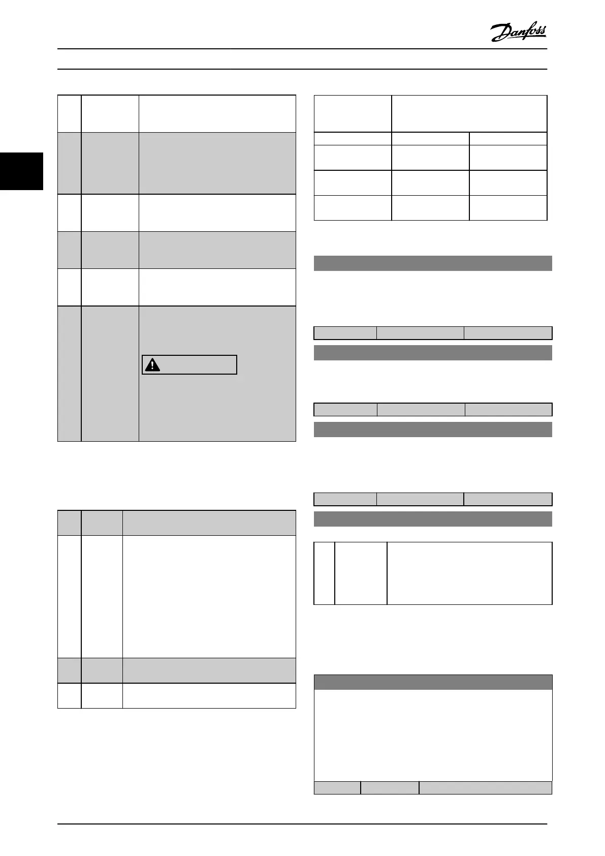
Table 3.15.
[202] Pump2
Running
See [201] Pump1 Running
[203] Pump3
Running
See [201] Pump1 Running
Setting in
parameter group
5-3* Digital Outputs
Setting in parameter 25-06 Number of
Pumps
[0] No [1] Yes
[200] Pump 1
Running
Controlled by
RELAY1
Frequency converter
controlled
[201] Pump 2
Running
Controlled by
RELAY2
Controlled by
RELAY1
[203] Pump 3
Running
Controlled by
RELAY3
Controlled by
RELAY2
Table 3.15 Settings
5-30 Terminal 27 Digital Output
This parameter has the options described in chapter 3.7.10 5-3*
Digital Outputs. This parameter is active when VLT
®
General
Purpose I/O MCB 101 is mounted in the frequency converter.
Option: Function:
[0] * No operation
5-31 Terminal 29 Digital Output
This parameter has the options described in chapter 3.7.10 5-3*
Digital Outputs. The default option is listed.
Option: Function:
[0] * No operation
5-32 Term X30/6 Digi Out (MCB 101)
This parameter has the options described in chapter 3.7.10 5-3*
Digital Outputs. This parameter is active when VLT
®
General
Purpose I/O MCB 101 is mounted in the frequency converter.
Option: Function:
[0] * No operation
5-33 Term X30/7 Digi Out (MCB 101)
Option: Function:
[0] * No operation This parameter has the same options dened
in parameter group 5-3* Digital Inputs. This
parameter is active when VLT
®
General
Purpose I/O MCB 101 is mounted in the
frequency converter.
3.7.11 5-4* Relays
Parameters for conguring the timing and the output
functions for the relays.
5-40 Function Relay
Array [8]
(Relay 1 [0], Relay 2 [1]
Option MCB 105: Relay 7 [6], Relay 8 [7] and Relay 9 [8]).
Select options to dene the function of the relays.
The selection of each mechanical relay is realized in an array
parameter.
Option: Function:
[0] No operation
Parameter Descriptions
VLT
®
HVAC Drive FC 102
98 Danfoss A/S © 10/2019 All rights reserved. M0010001
33
 Loading...


