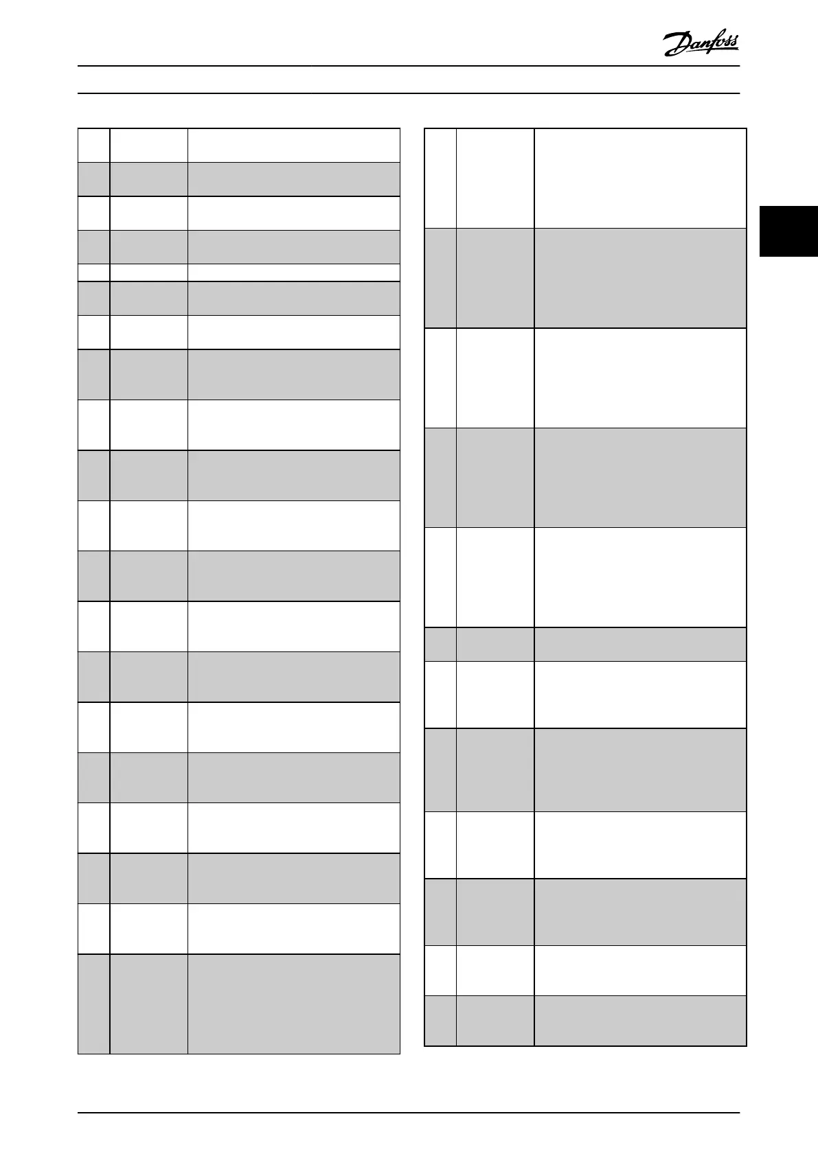
[35] External
Interlock
The external interlock function has been
activated via one of the digital inputs.
[40] Out of ref
range
[41] Below
reference low
[42] Above
reference high
[45] Bus Ctrl
[46] Bus Ctrl 1 if
timeout
[47] Bus Ctrl 0 if
timeout
[60] Comparator 0 See parameter group 13-1* Comparators. If
comparator 0 is evaluated as TRUE, the
output goes high. Otherwise, it is low.
[61] Comparator 1 See parameter group 13-1* Comparators. If
comparator 2 is evaluated as TRUE, the
output goes high. Otherwise, it is low.
[62] Comparator 2 See parameter group 13-1* Comparators. If
comparator 2 is evaluated as TRUE, the
output goes high. Otherwise, it is low.
[63] Comparator 3 See parameter group 13-1* Comparators. If
comparator 3 is evaluated as TRUE, the
output goes high. Otherwise, it is low.
[64] Comparator 4 See parameter group 13-1* Comparators. If
comparator 4 is evaluated as TRUE, the
output goes high. Otherwise, it is low.
[65] Comparator 5 See parameter group 13-1* Comparators. If
comparator 5 is evaluated as TRUE, the
output goes high. Otherwise, it is low.
[70] Logic Rule 0 See parameter group 13-4* Logic Rules. If
logic rule 0 is evaluated as TRUE, the
output goes high. Otherwise, it is low.
[71] Logic Rule 1 See parameter group 13-4* Logic Rules. If
logic rule 1 is evaluated as TRUE, the
output goes high. Otherwise, it is low.
[72] Logic Rule 2 See parameter group 13-4* Logic Rules. if
logic rule 2 is evaluated as TRUE, the
output goes high. Otherwise, it is low.
[73] Logic Rule 3 See parameter group 13-4* Logic Rules. If
logic rule 3 is evaluated as TRUE, the
output goes high. Otherwise, it is low.
[74] Logic Rule 4 See parameter group 13-4* Logic Rules. If
logic rule 4 is evaluated as TRUE, the
output goes high. Otherwise, it is low.
[75] Logic Rule 5 See parameter group 13-4* Logic Rules. if
logic rule 5 is evaluated as TRUE, the
output goes high. Otherwise, it is low.
[80] SL Digital
Output A
See parameter 13-52 SL Controller Action.
The input will go high whenever the
smart logic action [38] Set dig. out. A high
is executed. The input goes low whenever
the smart logic action [32] Set dig. out. A
low is executed.
[81] SL Digital
Output B
See parameter 13-52 SL Controller Action.
The input goes high whenever the smart
logic action [39] Set dig. out. Bhigh is
executed. The input goes low whenever
the smart logic action [33] Set dig. out. B
low is executed.
[82] SL Digital
Output C
See parameter 13-52 SL Controller Action.
The input goes high whenever the smart
logic action [40] Set dig. out. C high is
executed. The input goes low whenever
the smart logic action [34] Set dig. out. C
low is executed.
[83] SL Digital
Output D
See parameter 13-52 SL Controller Action.
The input goes high whenever the smart
logic action [41] Set dig. out. D high is
executed. The input goes low whenever
the smart logic action [35] Set dig. out. D
low is executed.
[84] SL Digital
Output E
See parameter 13-52 SL Controller Action.
The input goes high whenever the smart
logic action [42] Set dig. out. E high is
executed. The input goes low whenever
the smart logic action [36] Set dig. out. E
low is executed.
[85] SL Digital
Output F
See parameter 13-52 SL Controller Action.
The input goes high whenever the smart
logic action [43] Set dig. out. F high is
executed. The input goes low whenever
the smart logic action [37] Set dig. out. F
low is executed.
[160] No alarm The output is high when no alarm is
present.
[161] Running
reverse
The output is high when the frequency
converter is running counter clockwise
(the logical product of the status bits
running AND reverse).
[165] Local
reference
active
The output is high when
parameter 3-13 Reference Site=[2] Local or
when parameter 3-13 Reference Site=[0]
Linked to hand auto at the same time as
the LCP is in Hand mode.
[166] Remote
reference
active
The output is high when
parameter 3-13 Reference Site = [1] Remote
or [0] Linked to hand/auto while the LCP is
in Auto onmode.
[167] Start
command
active
The output is high when there is an active
start command (that is via digital input,
bus connection, [Hand on] or [Auto on]),
and no stop command is active.
[168] Drive in hand
mode
The output is high when the frequency
converter is in Hand mode (as indicated
by the LED light above [Hand On].
[169] Drive in auto
mode
The output is high when the frequency
converter is in Hand mode (as indicated
by the LED light above [Auto on].
Parameter Descriptions Programming Guide
M0010001 Danfoss A/S © 10/2019 All rights reserved. 97
3 3
 Loading...


