25-06 Number of Pumps
Range: Function:
2* [ 2 - 3 ] The number of pumps connected
to the cascade controller including
the variable–speed pump. If the
variable–speed pump is connected
directly to the frequency converter,
and the other xed–speed pumps
(lag pumps) are controlled by the 2
built-in relays, 3 pumps can be
controlled. If both the variable–
speed and xed–speed pumps are
to be controlled by built-in relays,
only 2 pumps can be connected.
If parameter 25-05 Fixed Lead Pump
is set to [0] No: 1 variable–speed
pump and 1 xed–speed pump,
both controlled by built-in relay. If
parameter 25-05 Fixed Lead Pump is
set to [1] Yes: 1 variable–speed
pump and 1 xed–speed pump
controlled by built-in relays.
1 lead pump, see
parameter 25-05 Fixed Lead Pump. 2
xed–speed pumps controlled by
built-in relays.
3.23.2 25-2* Bandwidth Settings
Parameters for setting the bandwidth within which the
pressure is allowed to operate before staging/destaging
xed speed pumps. Also includes various timers to stabilize
the control.
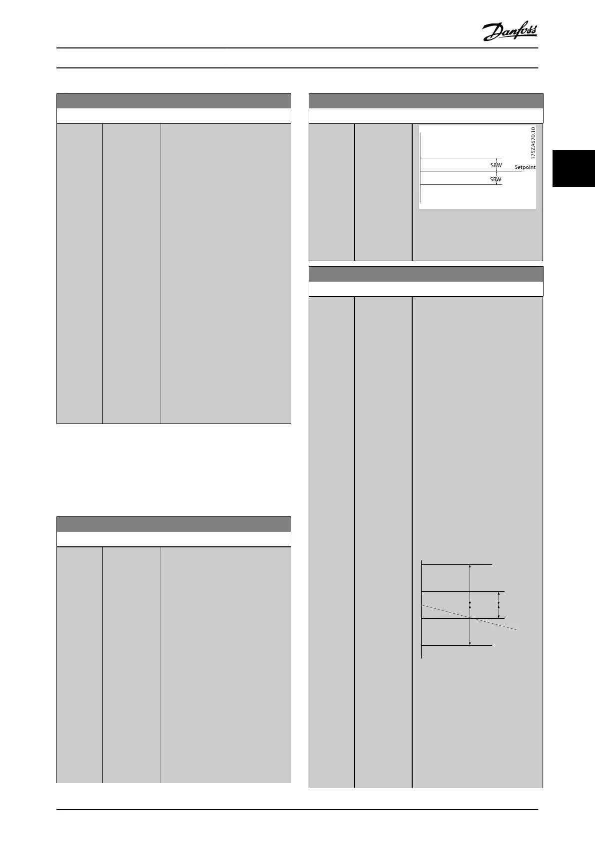
25-20 Staging Bandwidth
Range: Function:
10 %* [ 1 - par.
25-21 %]
Set the staging bandwidth (SBW)
percentage to accommodate
normal system pressure uctuation.
In cascade control systems, to avoid
frequent switching of xed speed
pumps, the desired system pressure
is typically kept within a bandwidth
rather than at a constant level.
The SBW is programmed as a
percentage of
parameter 20-13 Minimum Reference/
Feedb. and
parameter 20-14 Maximum
Reference/Feedb. For example, if the
setpoint is 5 bar and the SBW is set
to 10%, a system pressure between
4.5 and 5.5 bar is tolerated. No
staging or de-staging occur within
this bandwidth.
25-20 Staging Bandwidth
Range: Function:
Illustration 3.75 Staging
Bandwidth
25-21 Override Bandwidth
Range: Function:
100 %* [ par. 25-20 -
100 %]
When a large and quick change in
the system demand occurs (such as
a sudden water demand), the
system pressure rapidly changes
and an immediate staging or
destaging of a xed speed pump
becomes necessary to match the
requirement. The override
bandwidth (OBW) is programmed
to override the staging/destaging
timer (parameter 25-23 SBW Staging
Delay and parameter 25-24 SBW
Destaging Delay) for immediate
response.
Always program the OBW to a
higher value than the value set in
parameter 25-20 Staging Bandwidth.
The OBW is a percentage of
parameter 3-02 Minimum Reference
and parameter 3-03 Maximum
Reference.
SBW
SBW
Setpoint
Override Bandwidth
175ZA673.10
Illustration 3.77
Setting the OBW too close to the
SBW could defeat the purpose with
frequent staging at momentary
pressure changes. Setting the OBW
too high might lead to
unacceptably high or low pressure
in the system while the SBW timers
Parameter Descriptions Programming Guide
M0010001 Danfoss A/S © 10/2019 All rights reserved. 237
3 3
 Loading...


