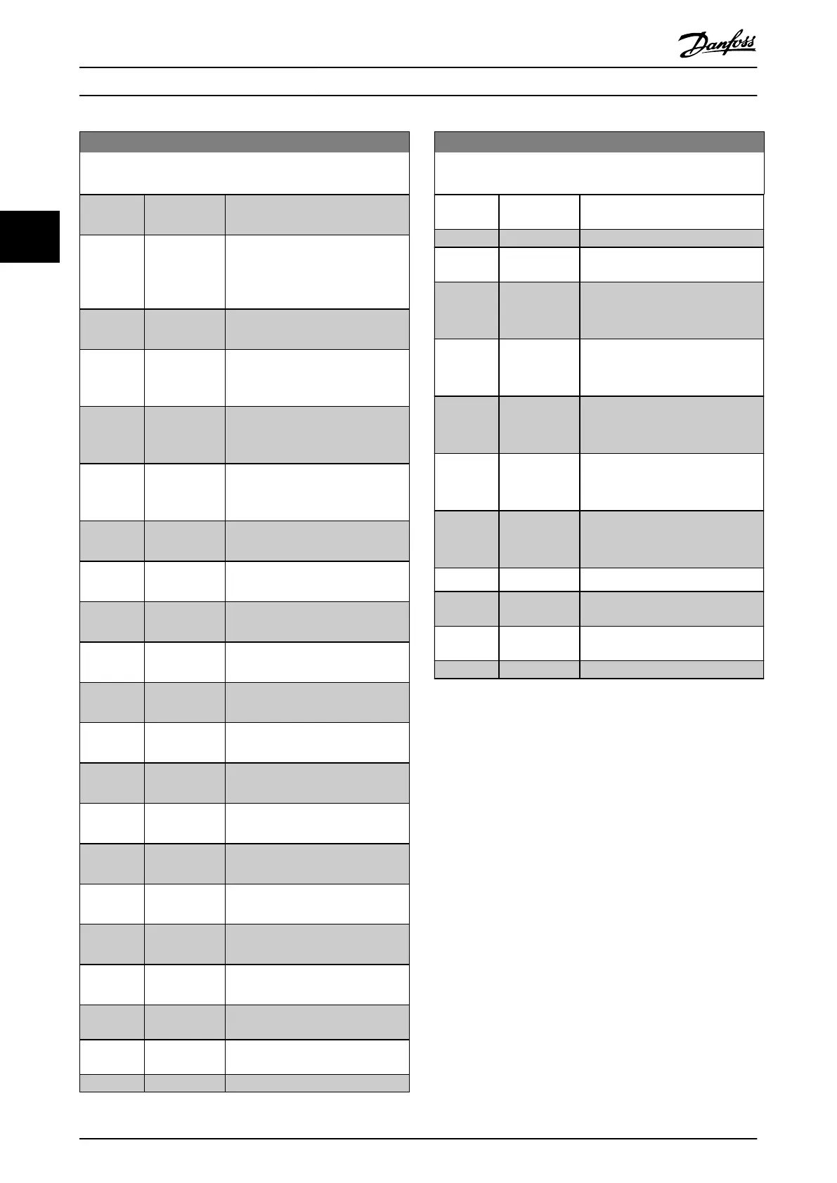
13-52 SL Controller Action
Array [20]
Option: Function:
[26] DC Brake Issues a DC stop command to the
frequency converter.
[27] Coast The frequency converter coasts
immediately. All stop commands
including the coast command stop
the SLC.
[28] Freeze output Freezes the output frequency of the
frequency converter.
[29] Start timer 0 Starts timer 0, see
parameter 13-20 SL Controller Timer
for further description.
[30] Start timer 1 Starts timer 1, see
parameter 13-20 SL Controller Timer
for further description.
[31] Start timer 2 Starts timer 2, see
parameter 13-20 SL Controller Timer
for further description.
[32] Set digital out
A low
Any output with digital output 1
selected is low (o).
[33] Set digital out
B low
Any output with digital output 2
selected is low (o).
[34] Set digital out
C low
Any output with digital output 3
selected is low (o).
[35] Set digital out
D low
Any output with digital output 4
selected is low (o).
[36] Set digital out
E low
Any output with digital output 5
selected is low (o).
[37] Set digital out
F low
Any output with digital output 6
selected is low (o).
[38] Set digital out
A high
Any output with digital output 1
selected is high (closed).
[39] Set digital out
B high
Any output with digital output 2
selected is high (closed).
[40] Set digital out
C high
Any output with digital output 3
selected is high (closed).
[41] Set digital out
D high
Any output with digital output 4
selected is high (closed).
[42] Set digital out
E high
Any output with digital output 5
selected is high (closed).
[43] Set digital out
F high
Any output with digital output 6
selected is high (closed).
[60] Reset Counter
A
Resets counter A to 0.
[61] Reset Counter
B
Resets counter B to 0.
[62] Counter A (up)
13-52 SL Controller Action
Array [20]
Option: Function:
[63] Counter A
(down)
[64] Counter B (up)
[65] Counter B
(down)
[70] Start Timer 3 Starts timer 3, see
parameter 13-20 SL Controller Timer
for further description.
[71] Start Timer 4 Starts timer 4, see
parameter 13-20 SL Controller Timer
for further description.
[72] Start Timer 5 Starts timer 5, see
parameter 13-20 SL Controller Timer
for further description.
[73] Start Timer 6 Starts timer 6, see
parameter 13-20 SL Controller Timer
for further description.
[74] Start Timer 7 Starts timer 7, see
parameter 13-20 SL Controller Timer
for further description.
[80] Sleep Mode Starts the sleep mode.
[90] Set ECB
Bypass Mode
[91] Set ECB Drive
Mode
[100] Reset Alarms
3.13.8 13-9* User-dened Alerts and
Readouts
Parameters in this group allow the conguration of
application-specic messages, warnings, and alarms.
Use the following parameters to congure the frequency
converter to show a message and perform an action when
a specic event occurs:
•
Parameter 13-90 Alert Trigger – the event that
triggers the user-dened action and message.
•
Parameter 13-91 Alert Action – the action that the
frequency converter performs when the event
dened in parameter 13-90 Alert Trigger occurs.
•
Parameter 13-92 Alert Text – the text that the
frequency converter shows in the display when
the event dened in parameter 13-90 Alert Trigger
occurs.
For example, consider the following use case:
If there is an active signal on digital input 32, the
frequency converter shows the message Valve 5 open and
ramps down to a stop.
To achieve this conguration, make the following settings:
Parameter Descriptions
VLT
®
HVAC Drive FC 102
144 Danfoss A/S © 10/2019 All rights reserved. M0010001
33
 Loading...


