•
Digital inputs.
•
Digital outputs.
•
Warning word.
•
Alarm word.
•
Status word.
•
Control word.
•
Extended status word.
Events are logged with value and time stamp in ms. The
time interval between 2 events depends on how often
events occur (maximum once every scan time). Data
logging is continuous, but if an alarm occurs, the log is
saved and the values can be viewed on the display. This
feature is useful, for example when carrying out service
following a trip. View the historic log contained in this
parameter via the serial communication port or via the
display.
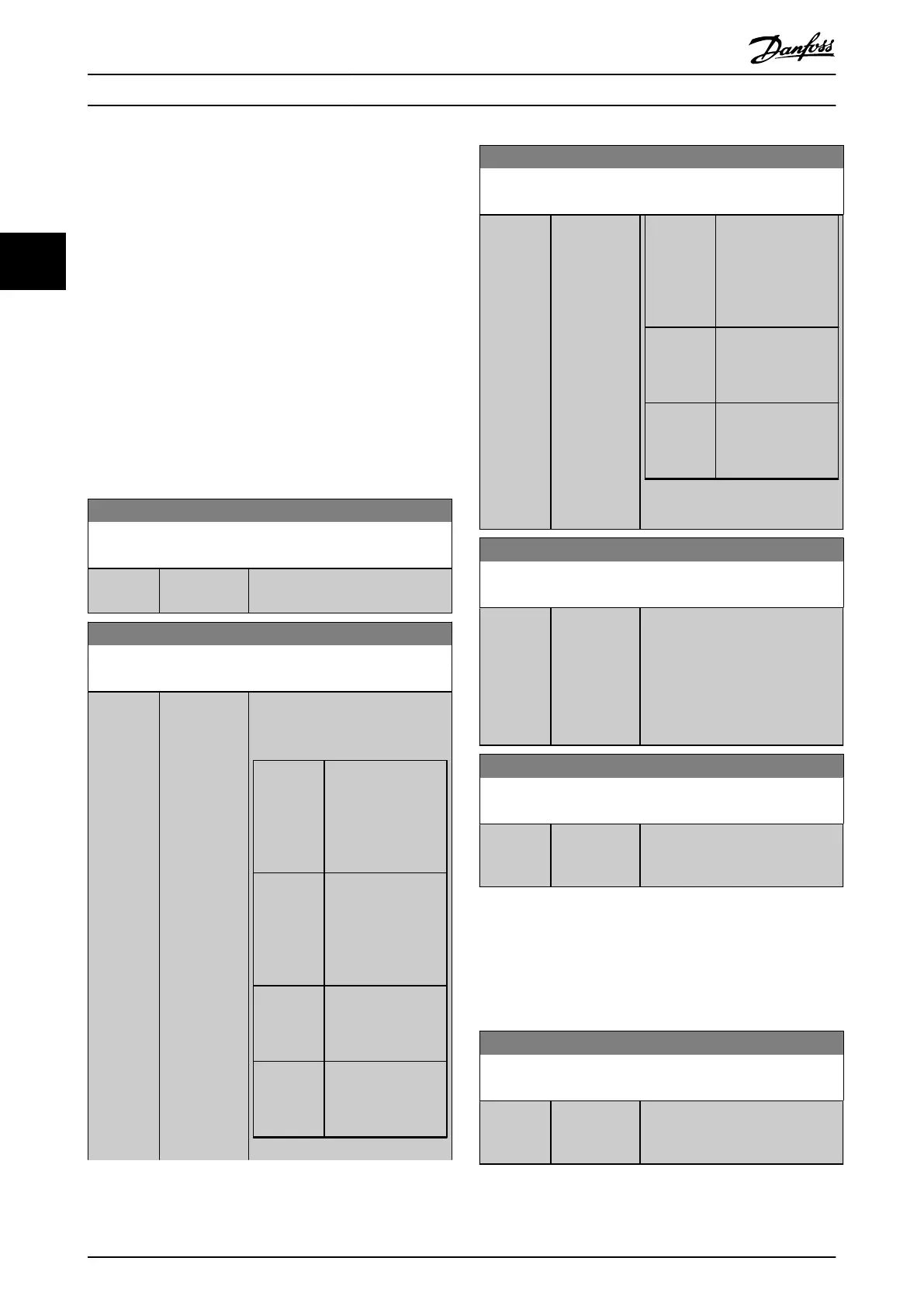
15-20 Historic Log: Event
Array [50]
Range: Function:
0* [0 - 255 ] View the event type of the logged
events.
15-21 Historic Log: Value
Array [50]
Range: Function:
0* [0 -
2147483647 ]
View the value of the logged event.
Interpret the event values according
to Table 3.21:
Digital
input
Decimal value. See
parameter 16-60 Digit
al Input for
description after
converting to binary
value.
Digital
output (not
monitored
in this SW
release)
Decimal value. See
parameter 16-66 Digit
al Output [bin] for a
description after
converting to binary
value.
Warning
word
Decimal value. See
parameter 16-92 Warn
ing Word for a
description.
Alarm word Decimal value. See
parameter 16-90 Alar
m Word for a
description.
15-21 Historic Log: Value
Array [50]
Range: Function:
Status word Decimal value. See
parameter 16-03 Statu
s Word for a
description after
converting to binary
value.
Control
word
Decimal value. See
parameter 16-00 Cont
rol Word for a
description.
Extended
status word
Decimal value. See
parameter 16-94 Ext.
Status Word for a
description.
Table 3.21 Logged Events
15-22 Historic Log: Time
Array [50]
Range: Function:
0 ms* [0 -
2147483647
ms]
View the time at which the logged
event occurred. Time is measured in
ms since frequency converter start.
The maximum value corresponds to
approximately 24 days, which
means that the count restarts at 0
after this time period.
15-23 Historic log: Date and Time
Array [50]
Range: Function:
Size
related*
[ 0 - 0 ] Array parameter; Date & Time 0–49:
This parameter shows when the
logged event occurred.
3.15.4 15-3* Alarm Log
Parameters in this group are array parameters where up to
10 fault logs can be viewed. 0 is the most recent logged
data, and 9 is the oldest. Fault codes, values, and time
stamp can be viewed for all logged data.
15-30 Alarm Log: Error Code
Array [10]
Range: Function:
0* [0 - 65535 ] View the fault code and look up its
meaning in chapter 4 Trouble-
shooting.
Parameter Descriptions
VLT
®
HVAC Drive FC 102
160 Danfoss A/S © 10/2019 All rights reserved. M0010001
33
 Loading...


