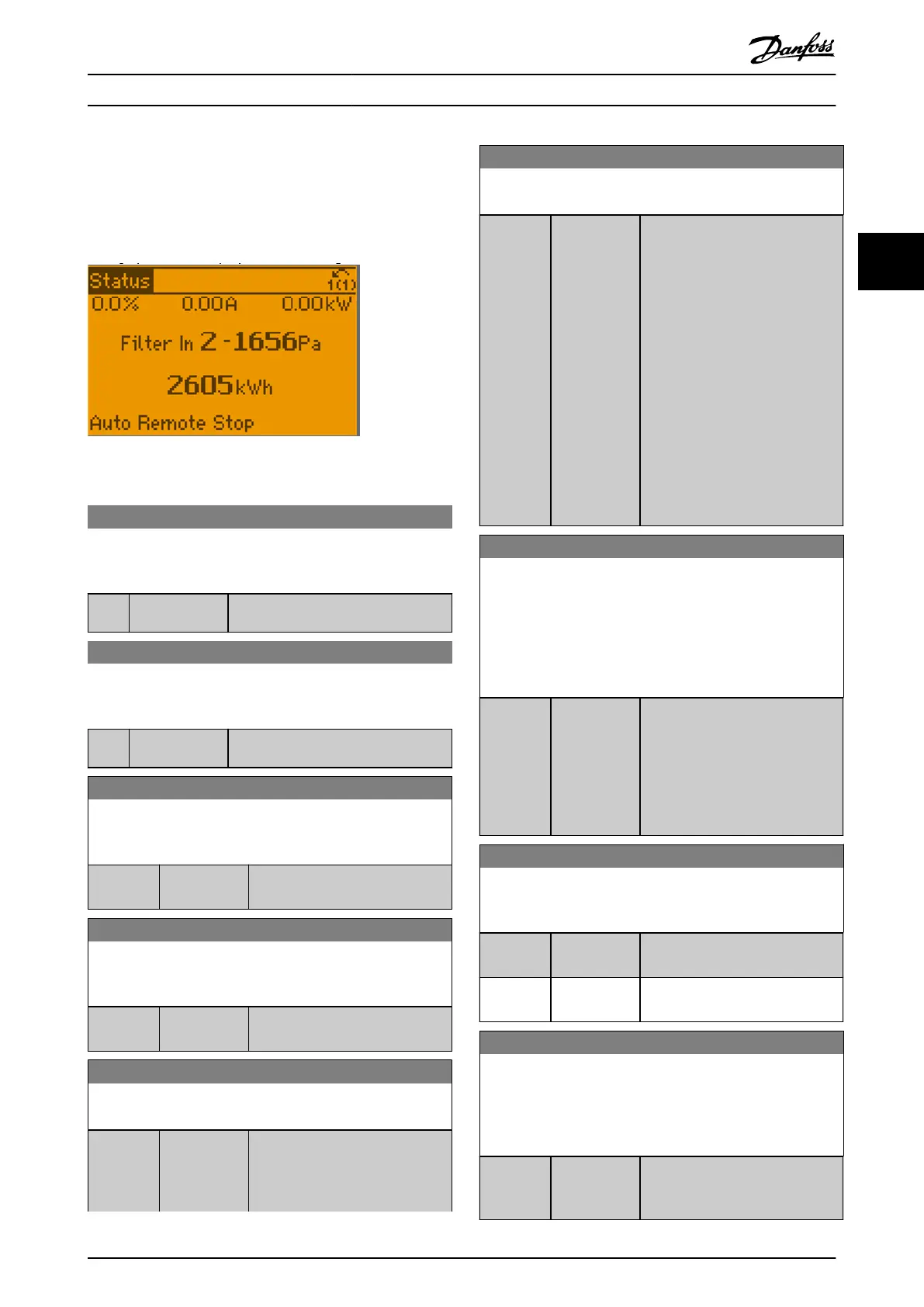
text followed by the sensor number and the actual
pressure value. The status line indicate status for all 4
sensors status or for individual sensors, where 1 indicate an
active On status. See illustration below.
Illustration 3.90 Pressure Sensor Data on the LCP
31-26 Pressure Sensor 1
Actual value and value range for sensor 1 is updated at power
up.
Range: Function:
0 Pa* [-500 - 500 Pa] Shows the readout of pressure sensor
1.
31-27 Pressure Sensor 2
Actual value and value range for sensor 2 is updated at power
up.
Range: Function:
0 Pa* [-500 - 500 Pa] Shows the readout of pressure sensor
2.
31-28 Pressure Sensor 3
Actual value and value range for sensor 3 is updated at power
up.
Range: Function:
-5000 Pa* [-5000 - 5000
Pa]
Shows the readout of pressure
sensor 3.
31-29 Pressure Sensor 4
Actual value and value range for sensor 4 is updated at power
up.
Range: Function:
-5000 Pa* [-5000 - 5000
Pa]
Shows the readout of pressure
sensor 4.
31-30 Press Sens Cmp State
Actual status state for all sensors.
Range: Function:
0* [0 - 255 ] Shows the value for all 4 sensors.
The state is an 8-digit binary value,
where 1 indicates an active status
(ON) and 0 indicates an inactive
31-30 Press Sens Cmp State
Actual status state for all sensors.
Range: Function:
status (OFF). Reading from right to
left, the rst 4 digits indicate the
alarms for the below-level
threshold, and the last 4 digits the
alarms for the above-level
threshold. For instance, counting
from right to left, sensor 1 for the
below-level threshold is at position
1, and sensor 1 for the above-level
threshold is at position 5.
The status information include
digital outputs or eldbus, as for
SLC control function. The
information can include all sensors
or individual sensor selection via
the SLC function.
31-31 Press Sens toggle
The pressure sensors can be congured for readouts. The
pressure sensor toggle function makes it possible to include all
active sensors in 1 readout, when the readout switches between
the dened sensors in a loop, starting from sensor 1 to sensor 4.
The individual sensor information is shown with sensor text,
number and value.
Range: Function:
0* [0 - 21 ] Shows the pressure text, number
and actual pressure value for all
active sensors. The readout switches
between sensors in a loop, going
from sensor 1 to sensor 4. The
sensor number is followed by a
hash sign.
31-32 Toggled Readout Conguration
Use this parameter, to congure sensors which are shown in
parameter 31-31 Press Sens toggle.
Option: Function:
[0] Disabled The addressed sensor is not shown
in parameter 31-31 Press Sens toggle.
[1] * Enabled The addressed sensor is shown in
parameter 31-31 Press Sens toggle.
31-33 Toggled Readout Text
Each of the sensors allows a customized text up to 11 characters.
Customizing of text enables better understanding of the sensor
pressure signal. This is a parameter array with 4 text strings, 1 for
each sensor.
Range: Function:
Size
related*
[0 - 12 ] Enter customized text as required.
The text is shown in
parameter 31-31 Press Sens toggle
Parameter Descriptions Programming Guide
M0010001 Danfoss A/S © 10/2019 All rights reserved. 259
3 3

 Loading...


