parameter group 22 Application Functions for air to volume
control calculation.
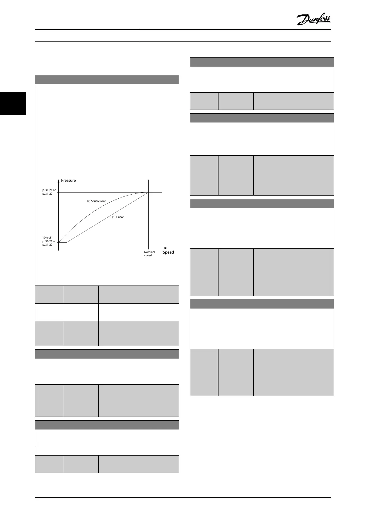
31-20 Pressure/Speed Curve Adjustment
The pressure status is based on individual thresholds levels
which are triggered when the pressure goes above or below the
threshold. The minimum and maximum values are working as
disable of the function (indicated in the LCP). The trigger levels
are dened at nominal speed operation and are adjusted to the
actual speed of the drive after dierent pressure curves. Select
the individual type of speed adjustment curve for the individual
threshold value, dened at nominal speed.
For options [1] Linear and [2] Square root, the pressure threshold
at 0 speed equals 10% of the value entered in
parameter 31-21 Below level threshold or parameter 31-22 Above
level threshold. See Illustration 3.90.
Illustration 3.90 Pressure/Speed Dependency
Option: Function:
[0] * None The pressure threshold is constant
and does not depend on speed.
[1] Linear The pressure threshold is propor-
tional to the speed.
[2] Square root The pressure threshold depends on
the speed. The dependency is
quadratic.
31-21 Below level threshold
Parameter array with 4 elements, 1 for each sensor. Default value
and value range depends on sensor version.
Range: Function:
Size
related*
[ -5000 -
5000 Pa]
Enter the lowest threshold level to
trigger pressure sensor status noti-
cations. The function is Disabled
when selecting the lowest value.
31-22 Above level threshold
Parameter array with 4 elements, 1 for each sensor. Default value
and value range depends on sensor version.
Range: Function:
Size
related*
[ -5000 -
5000 Pa]
Enter the threshold when pressure
levels exceed and notications are
31-22 Above level threshold
Parameter array with 4 elements, 1 for each sensor. Default value
and value range depends on sensor version.
Range: Function:
triggered. The function is Disabled
when selecting the highest value.
31-23 On Delay Time
Parameter array with 4 elements, 1for each sensor. An individual
On Delay time ensures that the actual conditions are active
before the status change.
Range: Function:
60 s* [0 - 3600 s] Enter the on delay time. When the
current pressure value remains
above or below the threshold after
the on delay time, notications are
triggered.
31-24 Reset Delay Time
A Reset Delay time enables an automatic reset when conditions
disappear after a certain time. The status reset can also be
managed by a local manual reset the via the LCP or eldbus
interface.
Range: Function:
9999 s* [0 - 9999 s] Enter the reset delay time, as the
time the actual value must be “o”
before resetting the status. When
entering the highest value , the
function is disabled, and a manual
reset is need via LCP or eldbus.
31-25 Pressure lter time constant
Parameter array with 4 elements, one for each sensor. A pressure
lter time constant adjusts the dynamic of the reaction to the
actual pressure input, to ensure reliable and stable status
generation.
Range: Function:
1 s* [0.01 - 60 s] Enter the pressure lter time
constant. A higher value make the
pressure signal more stable but less
dynamic. A lower value makes the
system more dynamic and allows
signal spikes to aect the control.
3.26.3 31-2** Readouts
Parameters in this group contain the actual pressure levels
and status information. The LCP can be congured to show
the values of these parameters in dierent display lines.
Use parameter 0-20 Display Line 1.1 Small to
parameter 0-24 Display Line 3 Large when conguring the
LCP to show dierent pressure values. The toggle function
allows to show multiple pressure signals in the same LCP
line. Each of the sensors can have individual customized
Parameter Descriptions
VLT
®
HVAC Drive FC 102
258 Danfoss A/S © 10/2019 All rights reserved. M0010001
33

 Loading...


