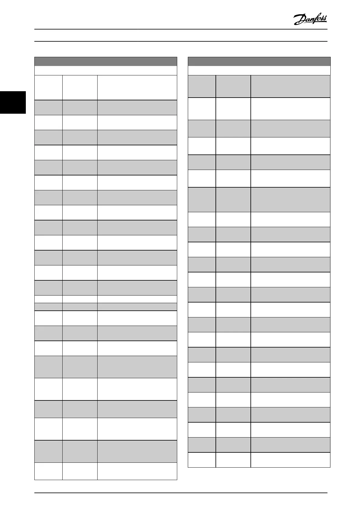
0-20 Display Line 1.1 Small
Option: Function:
[1835] Analog Out
X42/11 [V]
Shows the value of the signal
applied to terminal X42/11 on the
analog I/O card.
[1836] Analog Input
X48/2 [mA]
[1837] Temp. Input
X48/4
[1838] Temp. Input
X48/7
[1839] Temp. Input
X48/10
[1840] Analog Input
X49/1
[1841] Analog Input
X49/3
[1842] Analog Input
X49/5
[1843] Analog Out
X49/7
[1844] Analog Out
X49/9
[1845] Analog Out
X49/11
[1846] X49 Digital
Output [bin]
[1850] Sensorless
Readout [unit]
[1857] Air Pressure to
Flow Air Flow
[1860] Digital Input 2
[1870] Mains Voltage
[1871] Mains
Frequency
[1872] Mains
Imbalance
[1875] Rectier DC
Volt.
[2117] Ext. 1
Reference
[Unit]
The value of the reference for
extended closed-loop controller 1
[2118] Ext. 1
Feedback
[Unit]
The value of the feedback signal for
extended closed-loop controller 1
[2119] Ext. 1 Output
[%]
The value of the output from
extended closed-loop controller 1
[2137] Ext. 2
Reference
[Unit]
The value of the reference for
extended closed-loop controller 2
[2138] Ext. 2
Feedback
[Unit]
The value of the feedback signal for
extended closed-loop controller 2
[2139] Ext. 2 Output
[%]
The value of the output from
extended closed-loop controller 2
0-20 Display Line 1.1 Small
Option: Function:
[2157] Ext. 3
Reference
[Unit]
The value of the reference for
extended closed-loop controller 3
[2158] Ext. 3
Feedback
[Unit]
The value of the feedback signal for
extended closed-loop controller 3
[2159] Ext. 3 Output
[%]
The value of the output from
extended closed-loop controller 3
[2230] No-Flow
Power
The calculated no-ow power for
the actual operating speed
[2316] Maintenance
Text
[2580] Cascade Status Status for the operation of the
cascade controller
[2581] Pump Status Status for the operation of each
individual pump controlled by the
cascade controller
[3110] Bypass Status
Word
[3111] Bypass
Running Hours
[3126] Pressure
Sensor 1
[3127] Pressure
Sensor 2
[3128] Pressure
Sensor 3
[3129] Pressure
Sensor 4
[3130] Press Sens
Cmp State
[3131] Press Sens
toggle
[3401] PCD 1 Write
to MCO
[3402] PCD 2 Write
to MCO
[3403] PCD 3 Write
to MCO
[3404] PCD 4 Write
to MCO
[3405] PCD 5 Write
to MCO
[3406] PCD 6 Write
to MCO
[3407] PCD 7 Write
to MCO
[3408] PCD 8 Write
to MCO
[3409] PCD 9 Write
to MCO
 Loading...


