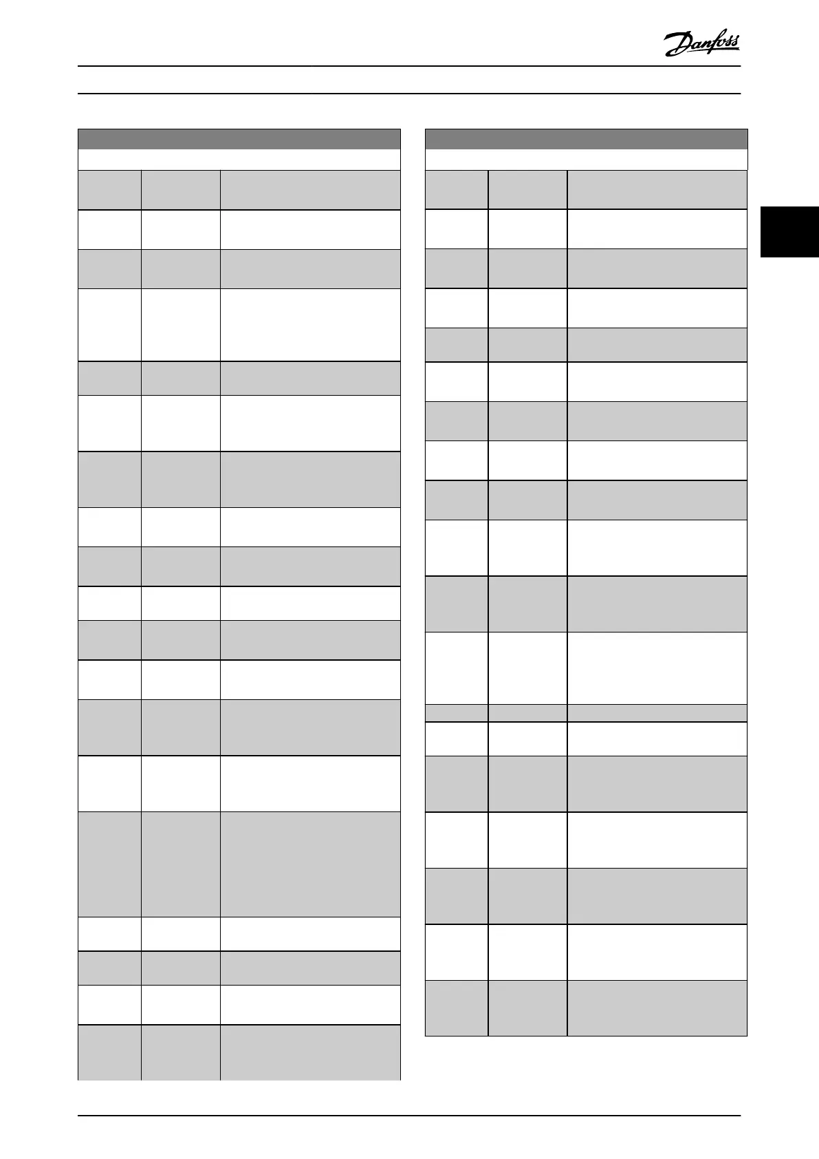
0-20 Display Line 1.1 Small
Option: Function:
[1662] Analog Input
53
Actual value at input 53 either as a
reference or protection value.
[1663] Terminal 54
Switch Setting
Setting of input terminal 54.
Current=0; Voltage=1.
[1664] Analog Input
54
Actual value at input 54 either as
reference or protection value.
[1665] Analog Output
42 [mA]
Actual value at output 42 in mA.
Use parameter 6-50 Terminal 42
Output to select the variable to be
represented by output 42.
[1666] Digital Output
[bin]
Binary value of all digital outputs.
[1667] Pulse Input
#29 [Hz]
Actual value of the frequency
applied at terminal 29 as a pulse
input.
[1668] Pulse Input
#33 [Hz]
Actual value of the frequency
applied at terminal 33 as a pulse
input.
[1669] Pulse Output
#27 [Hz]
Actual value of pulses applied to
terminal 27 in digital output mode.
[1670] Pulse Output
#29 [Hz]
Actual value of pulses applied to
terminal 29 in digital output mode.
[1671] Relay Output
[bin]
View the setting of all relays.
[1672] Counter A View the present value of counter
A.
[1673] Counter B View the present value of counter
B.
[1675] Analog In
X30/11
Actual value of the signal on input
X30/11 (general purpose I/O card.
Optional).
[1676] Analog In
X30/12
Actual value of the signal on input
X30/12 (general purpose I/O card.
Optional).
[1677] Analog Out
X30/8 [mA]
Actual value at output X30/8
(general purpose I/O card.
Optional). Use
parameter 6-60 Terminal X30/8
Output to select the variable to be
shown.
[1678] Analog Out
X45/1 [mA]
[1679] Analog Out
X45/3 [mA]
[1680] Fieldbus CTW
1
Control word (CTW) received from
the bus master.
[1682] Fieldbus REF 1 Main reference value sent with
control word via the serial
communications network, for
0-20 Display Line 1.1 Small
Option: Function:
example from the BMS, PLC, or
other master controller.
[1684] Comm. Option
STW
Extended eldbus communication
option status word.
[1685] FC Port CTW 1 Control word (CTW) received from
the bus master.
[1686] FC Port REF 1 Status word (STW) sent to the bus
master.
[1687] Bus Readout
Alarm/Warning
[1690] Alarm Word 1 or more alarms in a hex code
(used for serial communications).
[1691] Alarm Word 2 1 or more alarms in a hex code
(used for serial communications).
[1692] Warning Word 1 or more warnings in a hex code
(used for serial communications).
[1693] Warning Word
2
1 or more warnings in a hex code
(used for serial communications).
[1694] Ext. Status
Word
1 or more status conditions in a
hex code (used for serial communi-
cations).
[1695] Ext. Status
Word 2
1 or more status conditions in a
hex code (used for serial communi-
cations).
[1696] Maintenance
Word
The bits reect the status for the
programmed preventive
maintenance events in parameter
group 23-1* Maintenance.
[1697] Alarm Word 3
[1698] Warning Word
3
[1830] Analog Input
X42/1
Shows the value of the signal
applied to terminal X42/1 on the
analog I/O card.
[1831] Analog Input
X42/3
Shows the value of the signal
applied to terminal X42/3 on the
analog I/O card.
[1832] Analog Input
X42/5
Shows the value of the signal
applied to terminal X42/5 on the
analog I/O card.
[1833] Analog Out
X42/7 [V]
Shows the value of the signal
applied to terminal X42/7 on the
analog I/O card.
[1834] Analog Out
X42/9 [V]
Shows the value of the signal
applied to terminal X42/9 on the
analog I/O card.
 Loading...


