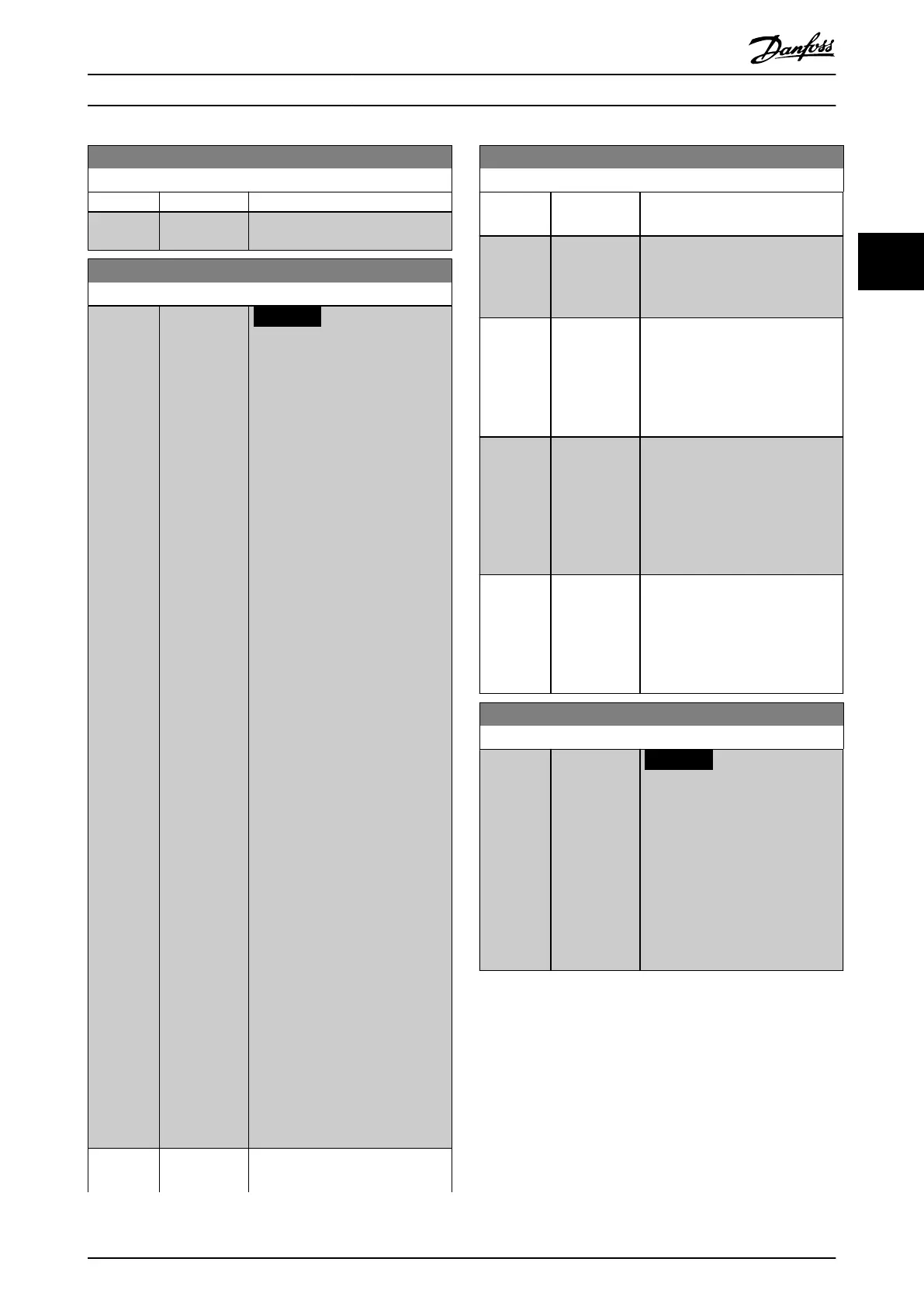
2-13 Brake Power Monitoring
Option: Function:
[14] Trip 600s
[15] Warning & trip
600s
2-15 Brake Check
Option: Function:
NOTICE
Remove a warning arising with
[0] O or [1] Warning by
cycling the mains supply.
Correct the fault rst. For [0]
O or [1] Warning, the
frequency converter keeps
running even if a fault is
found.
Select the type of test and
monitoring function to check the
connection to the brake resistor, or
whether a brake resistor is present,
and then show a warning or an
alarm if a fault occurs. The brake
resistor disconnection function is
tested during power-up. However,
the brake IGBT test is performed
when there is no braking. A
warning or trip disconnects the
brake function.
The testing sequence is as follows:
1. Measure the DC-link ripple
amplitude for 300 ms
without braking.
2. Measure the DC-link ripple
amplitude for 300 ms with
the brake turned on.
3. If the DC-link ripple
amplitude while braking is
lower than the DC-link
ripple amplitude before
braking +1%, the brake
check fails. If brake check
fails, a warning or alarm is
returned.
4. If the DC-link ripple
amplitude while braking is
higher than the DC-link
ripple amplitude before
braking +1%, the brake
check is OK.
[0] * O Monitors brake resistor and brake
IGBT for a short circuit during
2-15 Brake Check
Option: Function:
operation. If a short circuit occurs, a
warning appears.
[1] Warning Monitors brake resistor and brake
IGBT for a short circuit and runs a
test for brake resistor disconnection
during power-up.
[2] Trip Monitors for a short circuit or
disconnection of the brake resistor,
or a short circuit of the brake IGBT.
If a fault occurs, the frequency
converter cuts out while showing
an alarm (trip lock).
[3] Stop and trip Monitors for a short circuit or
disconnection of the brake resistor,
or a short circuit of the brake IGBT.
If a fault occurs, the frequency
converter ramps down to coast and
then trips. A trip lock alarm is
shown.
[4] AC brake Monitors for a short circuit or
disconnection of the brake resistor,
or a short circuit of the brake IGBT.
If a fault occurs, the frequency
converter performs a controlled
ramp down.
2-16 AC brake Max. Current
Range: Function:
Size
related*
[ 0 - par.
4-18 %]
NOTICE
Parameter 2-16 AC brake Max.
Current has no eect when
parameter 1-10 Motor
Construction = [1] PM, non-
salient SPM.
Enter the maximum permissible
current when using AC brake to
avoid overheating of motor
windings.
Parameter Descriptions Programming Guide
M0010001 Danfoss A/S © 10/2019 All rights reserved. 73
3 3
 Loading...


