compounds causes chemical processes on the frequency
converter
components.
Such
chemical
reactions rapidly affects and damages the
electronic components. In such environments, mount the
equipment in a cabinet with fresh air ventilation, keeping
aggressive gases away from the frequency converter.
An extra protection in such areas is a coating of the
printed circuit boards, which can be ordered as an option.
NOTE
Mounting
frequency
converters
in aggressive environments
increases the risk of stoppages and considerably reduces
the life of the frequency converter.
Before installing the frequency converter, check the
ambient air for liquids, particles, and gases. This is done by
observing existing installations in this environment. Typical
indicators of harmful airborne liquids are water or oil on
metal parts, or corrosion of metal parts.
Excessive dust particle levels are often found on instal-
lation cabinets and existing electrical installations. One
indicator of aggressive airborne gases is blackening of
copper rails and cable ends on existing installations.
2.4 Vibration and Shock
The frequency converter has been tested according to the
procedure based on the shown standards:
The frequency converter complies with requirements that
exist for units mounted on the walls and floors of
production premises, as well as in panels bolted to walls or
floors.
IEC/EN 60068-2-6 Vibration (sinusoidal) - 1970
IEC/EN 60068-2-64 Vibration, broad-band random
Table 2.3
2.5 Advantages
2.5.1 Why use a Frequency Converter for
Controlling Fans and Pumps?
A frequency converter takes advantage of the fact that
centrifugal fans and pumps follow the laws of propor-
tionality for such fans and pumps. For further information
see 2.5.3 Example of Energy Savings.
2.5.2 The Clear Advantage - Energy Savings
The clear advantage of using a frequency converter for
controlling the speed of fans or pumps lies in the
electricity savings.
When comparing with alternative control systems and
technologies, a frequency converter is the optimum energy
control system for controlling fan and pump systems.
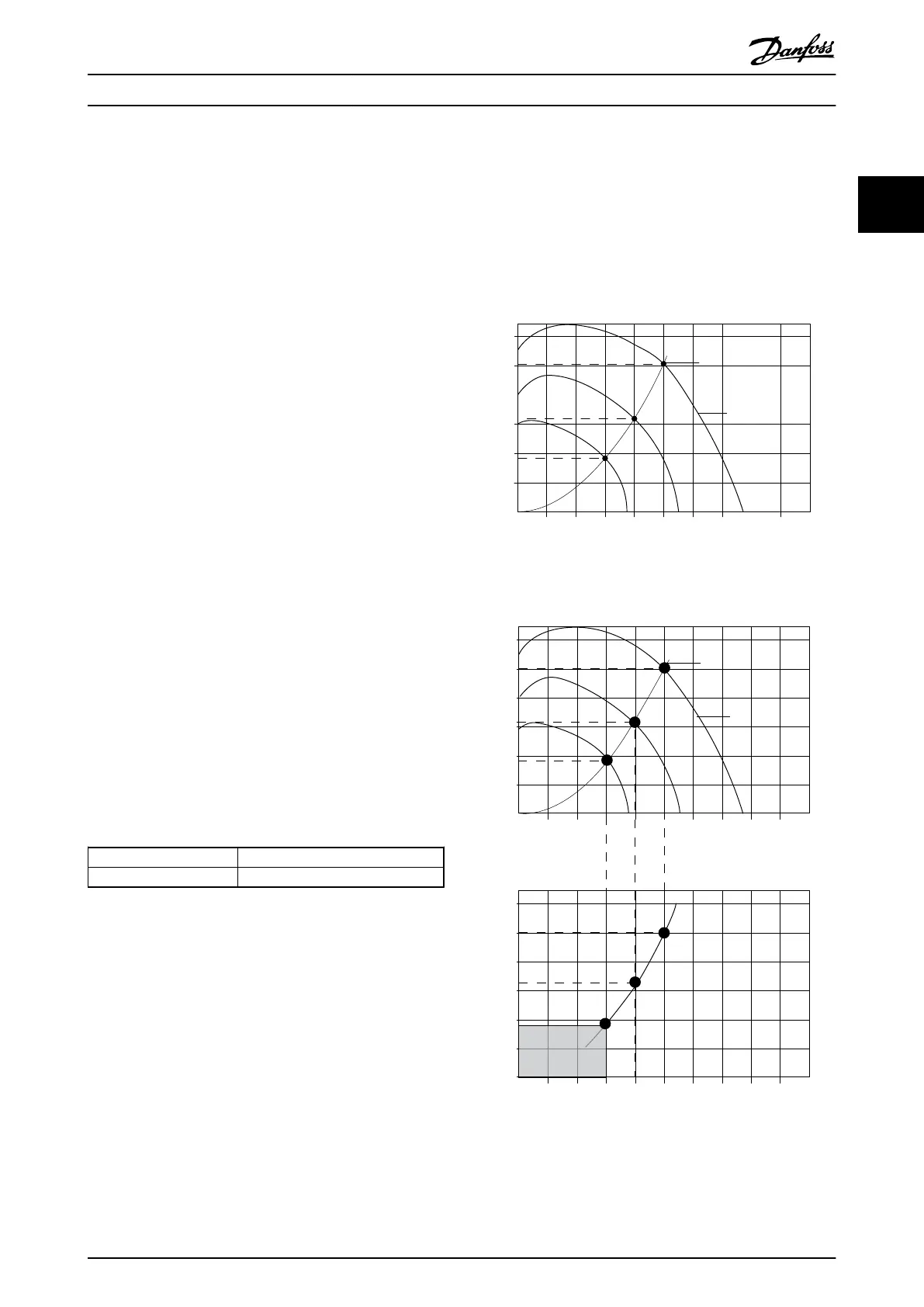
SYSTEM CURVE
FAN CURVE
PRESSURE%
130BA780.10
A
B
C
0
20
40
60
80
100
120
20 40 60 80 100 120 140 160 180
VOLUME%
Illustration 2.1 The graph is Showing Fan Curves (A, B, and C) for
Reduced Fan Volumes.
120
100
80
60
40
20
0
20 40 60 80 100 120 140 160 180
120
100
80
60
40
20
0 20 40 60 80 100 120 140 160 180
Voume %
Voume %
INPUT POWER % PRESSURE %
SYSTEM CURVE
FAN CURVE
A
B
C
130BA781.10
ENERGY
CONSUMED
Illustration 2.2 When using a frequency converter to reduce fan
capacity to 60% - more than 50% energy savings may be
obtained in typical applications.
Safety and Conformity
VLT
®
Micro Drive FC 51 Design Guide
MG02K202 - VLT
®
is a registered Danfoss trademark
13
2 2
Buy: www.ValinOnline.com | Phone 844-385-3099 | Email: CustomerService@valin.com

 Loading...


