6.9.1 Use of EMC-Correct Cables
Danfoss recommends braided screened/armoured cables to
optimise EMC immunity of the control cables and the EMC
emission from the motor cables.
The ability of a cable to reduce the in- and outgoing
radiation of electric noise depends on the transfer
impedance (Z
T
). The screen of a cable is normally designed
to reduce the transfer of electric noise; however, a screen
with a lower transfer impedance (Z
T
) value is more
effective than a screen with a higher transfer impedance
(Z
T
).
Transfer impedance (Z
T
) is rarely stated by cable manufac-
turers but it is often possible to estimate transfer
impedance (Z
T
) by assessing the physical design of the
cable.
Transfer impedance (Z
T
)
can be assessed on the basis of
the following factors:
- The conductibility of the screen material.
- The contact resistance between the individual
screen conductors.
- The screen coverage, that is, the physical area of
the cable covered by the screen - often stated as
a percentage value.
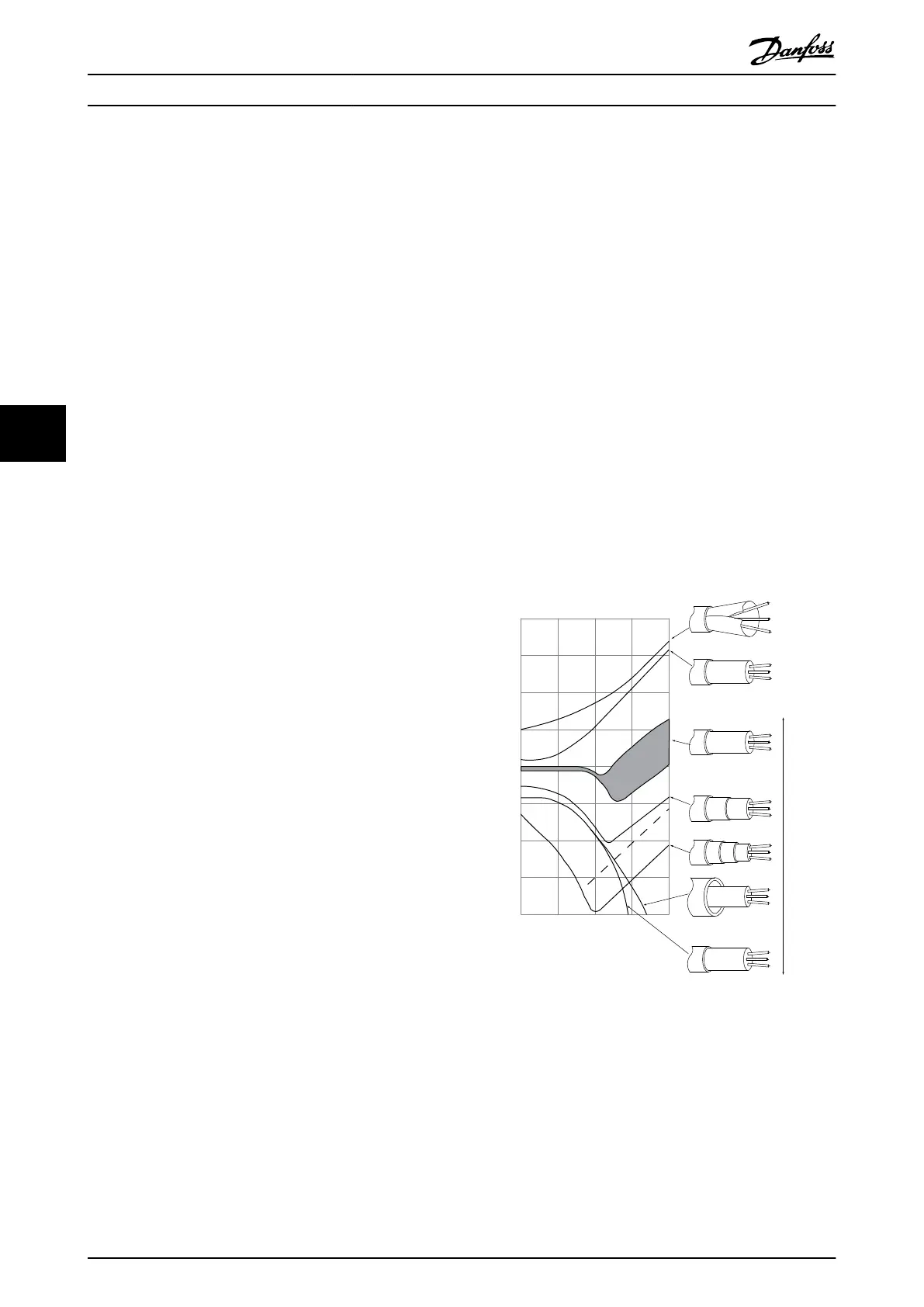
- Screen type, that is, braided or twisted pattern.
a. Aluminium-clad with copper wire.
b. Twisted copper wire or armoured steel wire cable.
c. Single-layer braided copper wire with varying
percentage screen coverage.
This is the typical Danfoss reference cable.
d. Double-layer braided copper wire.
e. Twin layer of braided copper wire with a
magnetic, screened/armoured intermediate layer.
f. Cable that runs in copper tube or steel tube.
g. Lead cable with 1.1 mm wall thickness.
175ZA166.13
0,01 0,1 1 10 100 MHz
10
10
10
1
10
10
10
10
10
a
b
c
d
e
f
g
The lower the Z the better the cable screening performance
Transfer impedance, Z
t
mOhm/m
Illustration 6.10
How to Install
VLT
®
Micro Drive FC 51 Design Guide
54 MG02K202 - VLT
®
is a registered Danfoss trademark
66
Buy: www.ValinOnline.com | Phone 844-385-3099 | Email: CustomerService@valin.com

 Loading...


