6.18 Motor Installation
6.18.1 Motor Insulation
For motor cable lengths ≤
the maximum cable length
listed in 9.1 Specifications, the following motor insulation
ratings are recommended because the peak voltage can be
up to twice the DC link voltage, 2.8 times the mains
voltage, due to transmission line effects in the motor
cable. If a motor has lower insulation rating it
recommended to use a dU/dt or sine wave filter.
Nominal Mains Voltage Motor Insulation
U
N
≤420 V
Standard U
LL
=1300 V
420 V<U
N
≤500
V Reinforced
U
LL
=1600 V
500 V<U
N
≤600 V Reinforced U
LL
=1800 V
600 V<U
N
≤690 V Reinforced U
LL
=2000 V
Table 6.10
6.19 Installation of Misc. Connections
6.19.1 RS-485 Bus Connection
One or more frequency converters can be connected to a
control (or master) using the RS-485 standardized interface.
Terminal 68 is connected to the P signal (TX+, RX+), while
terminal 69 is connected to the N signal (TX-,RX-).
If more than one frequency converter is connected to a
master, use parallel connections.
130BC011.10
68 69 68 69 68 69
RS 485
RS 232
USB
+
-
Illustration 6.19
In order to avoid potential equalizing currents in the
screen, earth the cable screen via terminal 61, which is
connected to the frame via an RC-link.
Bus termination
The RS-485 bus must be terminated by a resistor network
at both ends. For this purpose, set switch S801 on the
control card for "ON".
For more information, see the paragraph Switches S201,
S202, and S801.
Communication
protocol must be set to 8-30
Protocol
.
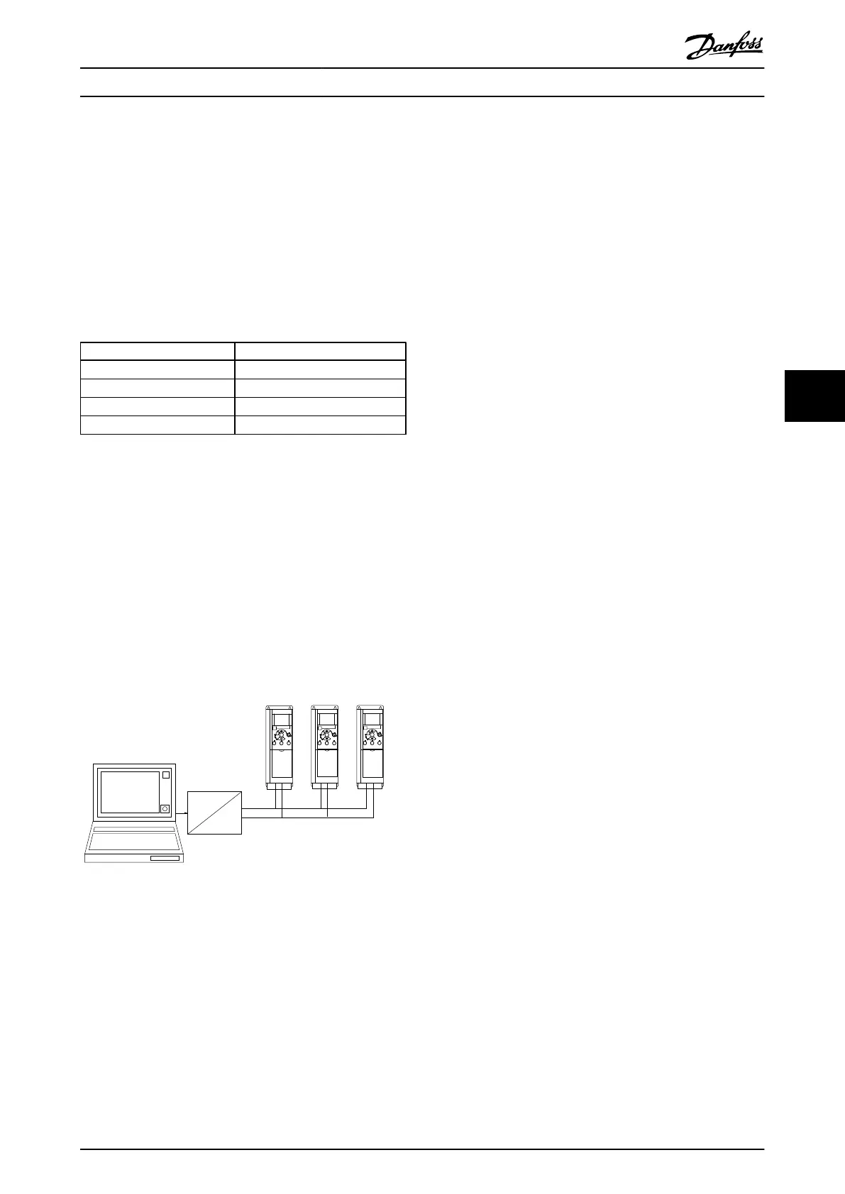
6.19.2
How to Connect a PC to the
Frequency Converter
To control or program the frequency converter from a PC,
install the PC-based Configuration Tool MCT 10 Set-up
Software.
MCT 10 Set-up Software
MCT 10 Set-up Software has been designed as an easy to
use interactive tool for setting parameters in our frequency
converters.
The PC-based Configuration Tool MCT 10 Set-up Software
will be useful for:
•
Planning a communication network off-line. MCT
10 Set-up Software contains a complete
frequency converter database
•
Commissioning frequency converters on line
•
Saving settings for all frequency converters
•
Replacing a frequency converter in a network
•
Expanding an existing network
•
Future developed frequency converters will be
supported
Save Drive Settings
1. Connect a PC to the unit via USB com port
2. Open PC-based Configuration Tool MCT 10 Set-up
Software
3. Choose “Read from drive”
4. Choose “Save as”
All parameters are now stored in the PC.
Load Drive Settings
1. Connect a PC to the unit via USB com port
2. Open PC-based Configuration Tool MCT 10 Set-up
Software
3. Choose “Open”– stored files is shown
4. Open the appropriate file
5. Choose “Write to drive”
All parameter settings are now transferred to the
frequency converter.
A separate manual for PC-based Configuration Tool MCT
10 Set-up Software is available.
How to Install
VLT
®
Micro Drive FC 51 Design Guide
MG02K202 - VLT
®
is a registered Danfoss trademark
61
6 6
Buy: www.ValinOnline.com | Phone 844-385-3099 | Email: CustomerService@valin.com

 Loading...


