6.7 Mains Connection
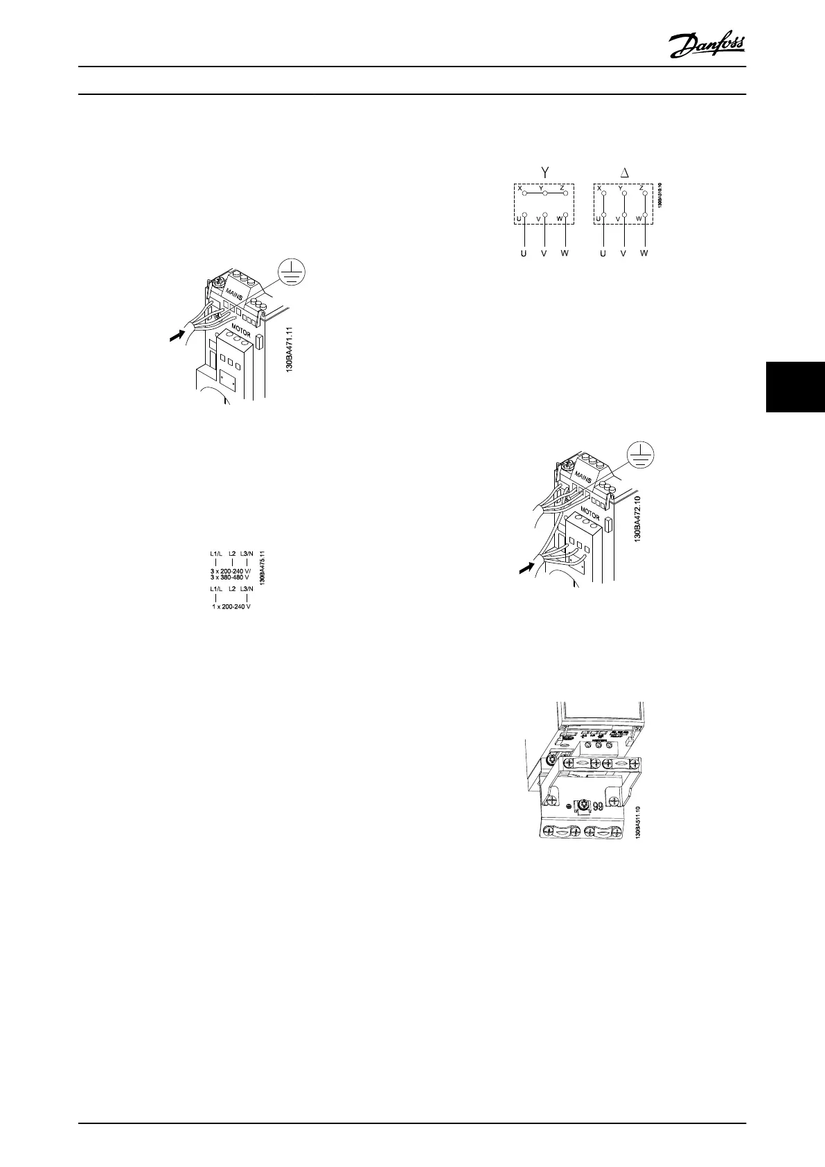
Step 1: Mount earth cable.
Step
2:
Mount wires in terminals L1/L, L2 and L3/N and
tighten.
Illustration 6.4 Mounting of Earth Cable and Mains Wires
For 3-phase connection, connect wires to all three
terminals.
For
single-phase connection, connect wires to terminals
L1/L and L3/N.
Illustration 6.5 Three-phase and Single-phase Wire Connections
6.8 Motor Connection
6.8.1 How to Connect the Motor
See 9 Specifications for correct dimensioning of motor
cable cross-section and length.
•
Use a shielded/armored motor cable to comply
with EMC emission specifications, and connect
this cable to both the decoupling plate and the
motor metal.
•
Keep motor cable as short as possible to reduce
the noise level and leakage currents.
For further details on mounting of the decoupling plate,
see instruction MI02B.
All
types of three-phased asynchronous standard motors
can be connected to the frequency converter. Normally,
small motors are star-connected (230/400 V, Δ/Y). Large
motors are delta-connected (400/690 V, Δ/Y). Refer to
motor nameplate for correct connection and voltage.
Illustration 6.6 Star and Delta Connections
Step 1: Mount the earth cable.
Step 2: Connect wires to terminals either in star or delta-
connection. See motor nameplate for further information.
Illustration 6.7 Mounting of Earth Cable and Motor Wires
For EMC correct installation, use optional de-coupling
plate,
see
5.2
Options for VLT Micro Drive
.
Illustration 6.8 Frequency Converter with De-coupling Plate
6.8.2 Motor Cables
See 9 Specifications for maximum dimensioning of motor
cable cross-section and length.
•
Use a screened/armoured motor cable to comply
with EMC emission specifications.
•
Keep the motor cable as short as possible to
reduce the noise level and leakage currents.
How to Install
VLT
®
Micro Drive FC 51 Design Guide
MG02K202 - VLT
®
is a registered Danfoss trademark
51
6 6
Buy: www.ValinOnline.com | Phone 844-385-3099 | Email: CustomerService@valin.com

 Loading...


