6.5 Electrical Installation in General
NOTE
All
cabling
must
comply with national and local
regulations on cable cross-sections and ambient
temperature. Copper conductors required, (60-75 °
C)
recommended.
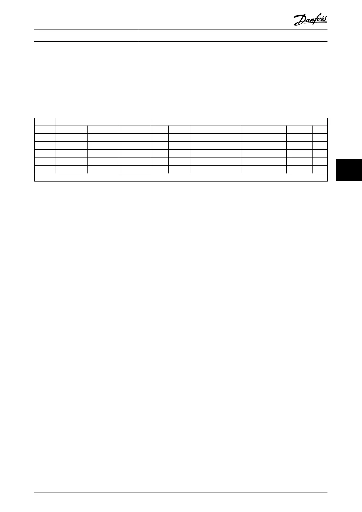
Power
[kW] Torque [Nm]
Frame 1x200-240 V 3x200-240 V 3x380-480 V Line Motor DC connection/Brake Control Terminals Earth Relay
M1 0.18-0.75 0.25-0.75 0.37-0.75 1.4 0.7
Spade
1)
0.15 3 0.5
M2 1.5 1.5 1.5-2.2 1.4 0.7
Spade
1)
0.15 3 0.5
M3 2.2 2.2-3.7 3.0-7.5 1.4 0.7
Spade
1)
0.15 3 0.5
M4 11.0-15.0 1.3 1.3 1.3 0.15 3 0.5
M5 18.5-22.0 1.3 1.3 1.3 0.15 3 0.5
1)
Spade connectors (6.3 mm Faston plugs)
Table 6.2 Tightening of Terminals
How to Install
VLT
®
Micro Drive FC 51 Design Guide
MG02K202 - VLT
®
is a registered Danfoss trademark
49
6 6
Buy: www.ValinOnline.com | Phone 844-385-3099 | Email: CustomerService@valin.com

 Loading...


