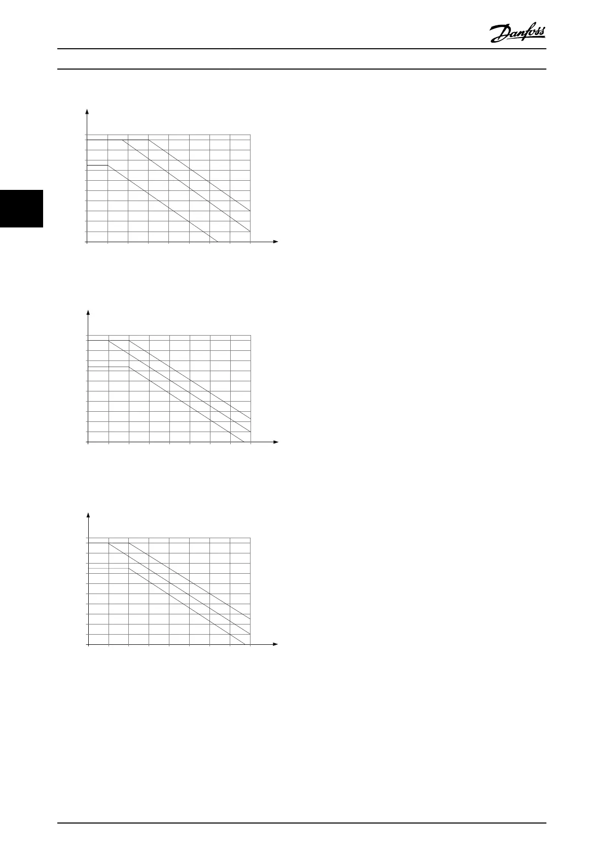
M3 400 V
fsw[kHz]20 64 108 1412
0
10 %
20
%
30 %
40 %
50 %
60 %
70 %
80 %
90 %
100 %
110
%
Iout [%]
16
40 ℃
45 ℃
50 ℃
130BC033.10
Illustration 4.40
M4 400 V
fsw[kHz]20 64 108 1412
0
10 %
20
%
30 %
40 %
50 %
60 %
70 %
80 %
90 %
100 %
110
%
Iout [%]
16
40 ℃
45 ℃
50 ℃
130BC034.10
Illustration 4.41
M5 400 V
fsw[kHz]20 64 108 1412
0
10 %
20
%
30 %
40 %
50 %
60 %
70 %
80 %
90 %
100 %
110
%
Iout [%]
16
40 ℃
45 ℃
50 ℃
130BC035.10
Illustration 4.42
4.2.3 Derating for Low Air Pressure
The cooling capability of air is decreased at low air
pressure.
For
altitudes above 2000 m, contact Danfoss regarding
PELV.
Below 1000 m altitude no de-rating is necessary but above
1000 m the ambient temperature or the maximum output
current should be decreased.
Decrease the output by 1% per 100 m altitude above 1000
m or reduce the max. ambient temperature by 1 degree
per 200 m.
4.2.4 Automatic Adaptations to Ensure
Performance
The frequency converter constantly checks for critical levels
of internal temperature, load current, high voltage on the
intermediate circuit and low motor speeds. As a response
to a critical level, the frequency converter can adjust the
switching frequency and/or change the switching pattern
in order to ensure the performance of the frequency
converter. The capability automatically to reduce the
output current extends the acceptable operating
conditions even further.
4.2.5 Derating for Running at Low Speed
When a motor is connected to a frequency converter, it is
necessary to check that the cooling of the motor is
adequate. The level of heating depends on the load on the
motor, as well as the operating speed and time.
Constant torque applications (CT mode)
A problem may occur at low RPM values in constant
torque applications. In a constant torque application a
motor may over-heat at low speeds due to less cooling air
from the motor integral fan.
Therefore, if the motor is to be run continuously at an RPM
value lower than half of the rated value, the motor must
be supplied with additional air-cooling (or a motor
designed for this type of operation may be used).
An alternative is to reduce the load level of the motor by
choosing a larger motor. However, the design of the
frequency converter puts a limit to the motor size.
VLT
®
Micro Drive Selection VLT
®
Micro Drive FC 51 Design Guide
42 MG02K202 - VLT
®
is a registered Danfoss trademark
44
Buy: www.ValinOnline.com | Phone 844-385-3099 | Email: CustomerService@valin.com

 Loading...


