8.10.6 Preset Multiple Registers (10 HEX)
Description
This function presets values into a sequence of holding
registers.
Query
The query message specifies the register references to be
preset. Register addresses start at zero, that is, register 1 is
addressed as 0. Example of a request to preset two
registers (set 1-24 Motor Current to 738 (7.38 A)):
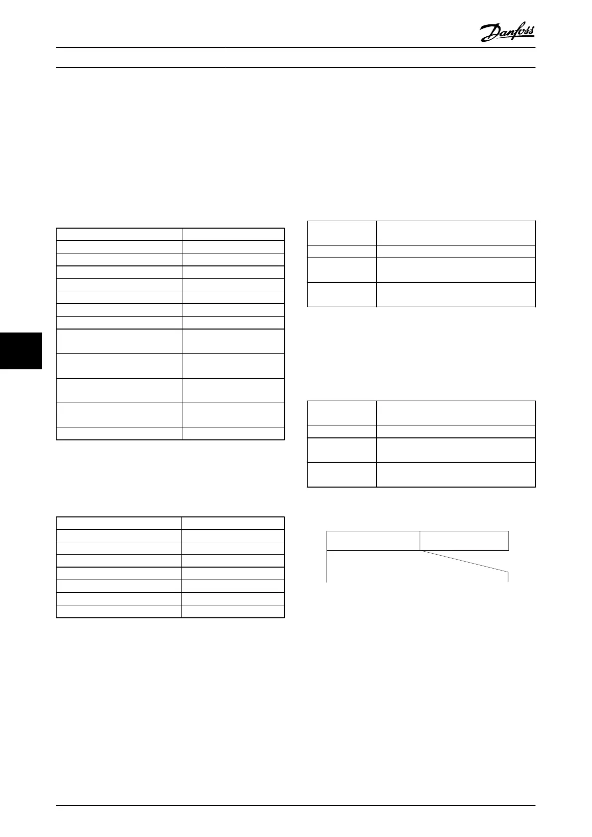
Field Name Example (HEX)
Slave Address 01
Function 10
Starting Address HI 04
Starting Address LO 19
No. of Registers HI 00
No. of registers LO 02
Byte Count 04
Write Data HI
(Register 4: 1049)
00
Write Data LO
(Register 4: 1049)
00
Write Data HI
(Register 4: 1050)
02
Write Data LO
(Register 4: 1050)
E2
Error Check (CRC) -
Table 8.32
Response
The
normal
response returns the slave address, function
code, starting address, and quantity of registers preset.
Field Name Example (HEX)
Slave Address 01
Function 10
Starting Address HI 04
Starting Address LO 19
No. of Registers HI 00
No. of registers LO 02
Error Check (CRC) -
Table 8.33
8.11 FC Drive Control Profile
8.11.1 Control Word According to FC
Profile (8-10 Protocol = FC profile)
Modbus Holding Register numbers for Input data – CTW
and REF – and Output data – STW and MAV – are defined
in Table 8.34
:
50000
Input data Frequency converter Control Word register
(CTW)
50010 Input data Bus Reference register (REF)
50200 Output data Frequency converter Status Word register
(STW)
50210 Output data Frequency converter Main Value register
(MAV)
Table 8.34
In VLT Micro Drives after the software version 2.32 the new
feature has been implemented by copying the Input/
Output data to also be available in a lower holding register
areas:
02810 Input data Frequency converter Control Word register
(CTW)
02811 Input data Bus Reference register (REF)
02910 Output data Frequency converter Status Word register
(STW)
02911 Output data Frequency converter Main Value register
(MAV)
Table 8.35
Speed ref.CTW
Master-slave
130BA274.10
15 14 13 12 11 10 9 8 7 6 5 4 3 2 1 0
Bit
no.:
Illustration 8.14
RS-485 Installation and Set...
VLT
®
Micro Drive FC 51 Design Guide
84 MG02K202 - VLT
®
is a registered Danfoss trademark
88
Buy: www.ValinOnline.com | Phone 844-385-3099 | Email: CustomerService@valin.com

 Loading...


