6.13 Electrical Installation and Control Cables
Terminal number Terminal description Parameter number Factory default
1+2+3 Terminal 1+2+3 - Relay1 5-40 No operation
12 Terminal 12 Supply - +24 V DC
18 Terminal 18 Digital Input 5-10 Start
19 Terminal 19 Digital Input 5-11 Reversing
20 Terminal 20 Common Digital Ground - Common
27 Terminal 27 Digital Input 5-12 Reset
29 Terminal 29 Digital Input 5-13 Jog
33 Terminal 33 Digital Input 5-15 Preset ref bit 0
42
Terminal 42 Analog Output/Digital
Output
6-9* No operation
50 Terminal 50 Supply for Analog Input - +10 V DC
53
Terminal 53 Analog Input (Voltage or
Current)
3-15/6-1* Reference
55 Terminal 55 Common Analog Ground - Common
60 Terminal 60 Current Input 3-16/6-2* Reference
Table 6.4 Terminal Connections
Very long control cables and analog signals may, in rare
cases and depending on installation, result in 50/60 Hz
earth loops due to noise from mains supply cables.
If this occurs, break the screen or insert a 100 nF capacitor
between screen and chassis.
NOTE
The
common
of
digital/analog inputs and outputs should
be connected to separate common terminals 20, 39, and
55. This avoids ground current interference among groups.
For example, it avoids switching on digital inputs
disturbing analog inputs.
NOTE
Control cables must be screened/armoured.
6.14 Control Terminals
6.14.1 Access to Control Terminals
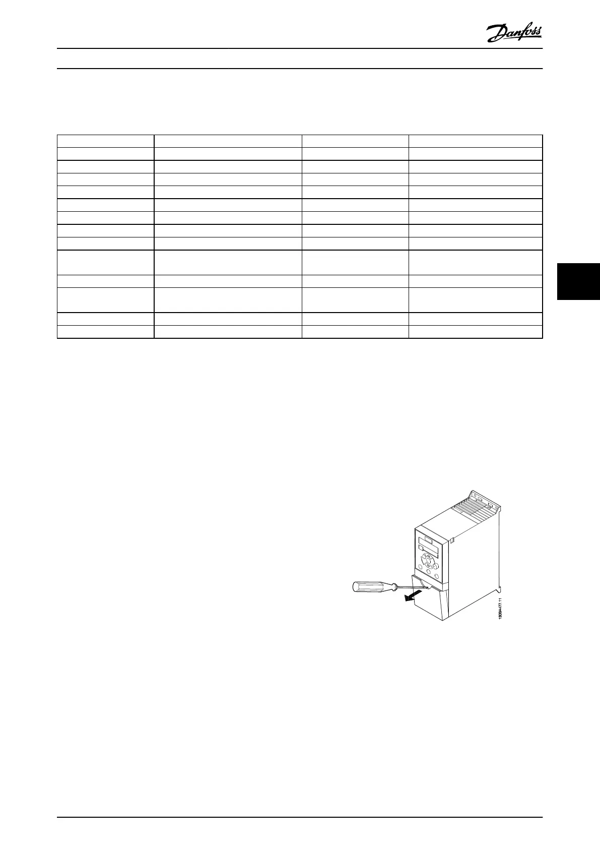
All control cable terminals are located underneath the
terminal cover in front of the frequency converter. Remove
the terminal cover using a screwdriver.
Illustration 6.13 Removing Terminal Cover
NOTE
See
back of terminal cover for outlines of control terminals
and switches.
How to Install
VLT
®
Micro Drive FC 51 Design Guide
MG02K202 - VLT
®
is a registered Danfoss trademark
57
6 6
Buy: www.ValinOnline.com | Phone 844-385-3099 | Email: CustomerService@valin.com

 Loading...


