1.1.2 Available Literature
NOTE
This design guide contains the basic information necessary
for installing and running the frequency converter.
Danfoss technical literature is available in print from local
Danfoss Sales Offices or online at: Danfoss
website /
BusinessAreas/DrivesSolutions/Documentations
-
VLT Micro Drive FC 51 Quick Guide, MG02B
-
VLT Micro Drive FC 51 Programming Guide, MG02C
-
FC 51 LCP Mounting Instruction, MI02A
-
FC 51 De-coupling Plate Mounting Instruction,
MI02B
-
FC 51 Remote Mounting Kit Mounting Instruction,
MI02C
-
FC 51 DIN Rail Kit Mounting Instruction, MI02D
-
FC 51 IP21 Kit Mounting Instruction, MI02E
-
FC 51 Nema1 Kit Mounting Instruction, MI02F
-
FC 51 Line Filter MCC 107 Installation Instruction,
MI02U
1.1.3 Symbols
The following symbols are used in this manual.
WARNING
Indicates a potentially hazardous situation which, if not
avoided, could result in death or serious injury.
CAUTION
Indicates a potentially hazardous situation which, if not
avoided, may result in minor or moderate injury. It may
also be used to alert against unsafe practices.
CAUTION
Indicates
a
situation
that may result in equipment or
property-damage-only accidents.
NOTE
Indicates highlighted information that should be regarded
with attention to avoid mistakes or operate equipment at
less than optimal performance.
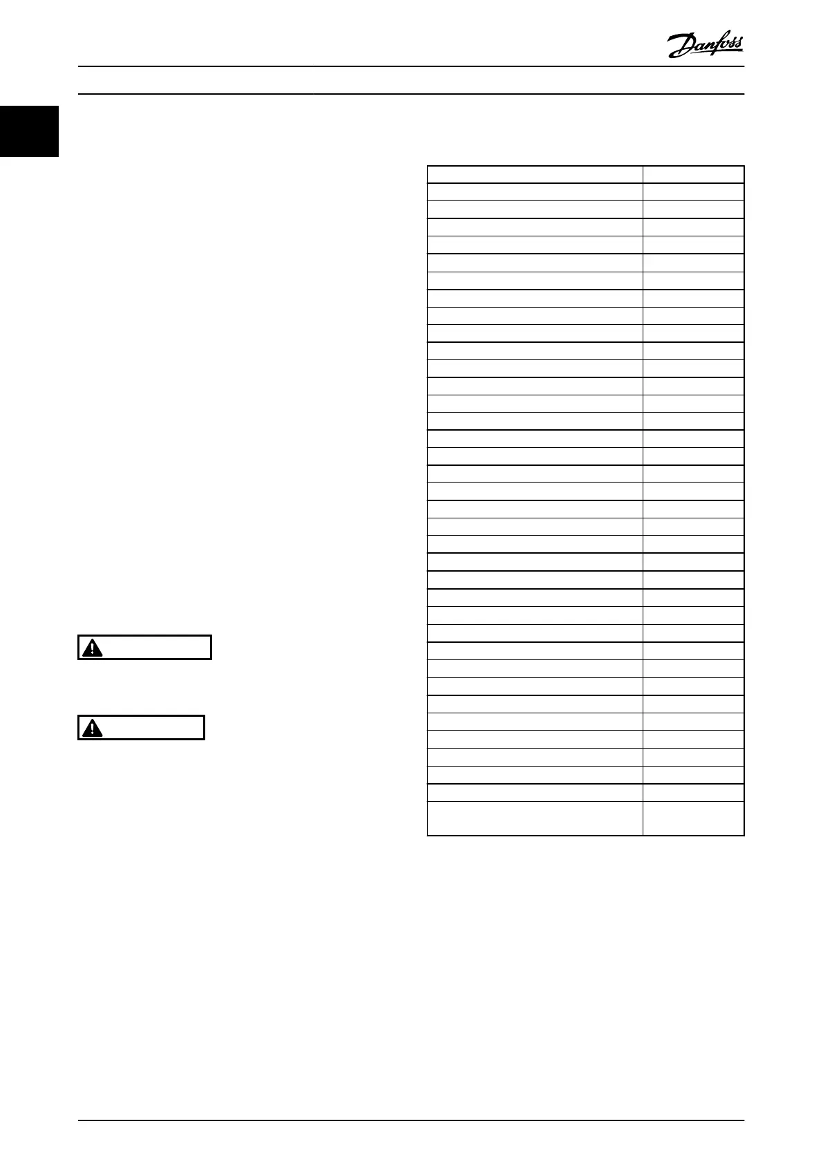
1.1.4 Abbreviations
Alternating current AC
American wire gauge AWG
Ampere/AMP A
Automatic Motor Tuning AMT
Current limit I
LIM
Degrees Celsius
°
C
Direct
current DC
Electro Magnetic Compatibility EMC
Electronic Thermal Relay ETR
Frequency Converter FC
Gram g
Hertz Hz
Kilohertz kHz
Local Control Panel
Meter m
Millihenry Inductance mH
Milliampere mA
Millisecond ms
Minute min
Motion Control Tool MCT
Nanofarad nF
Newton Meters Nm
Nominal motor current I
M,N
Nominal motor frequency f
M,N
Nominal motor power P
M,N
Nominal motor voltage U
M,N
Protective Extra Low Voltage PELV
Printed Circuit Board PCB
Rated Inverter Output Current I
INV
Revolutions Per Minute RPM
Regenerative terminals Regen
Second s
Synchronous Motor Speed n
s
Torque limit T
LIM
Volts V
The maximum output current I
VLT,MAX
The rated output current supplied by the
frequency
converter
I
VLT,N
Table 1.3
How to Read this Design Gui...
VLT
®
Micro Drive FC 51 Design Guide
6 MG02K202 - VLT
®
is a registered Danfoss trademark
11
Buy: www.ValinOnline.com | Phone 844-385-3099 | Email: CustomerService@valin.com

 Loading...


