8.4.10 Parameter Value (PWE)
The parameter value block consists of 2 words (4 bytes),
and the value depends on the defined command (AK). The
master prompts for a parameter value when the PWE block
contains no value. To change a parameter value (write),
write the new value in the PWE block and send from the
master to the slave.
When a slave responds to a parameter request (read
command), the present parameter value in the PWE block
is transferred and returned to the master. If a parameter
contains several data options, e.g. 0-01 Language, select
the
data value by entering the value in the PWE block.
Serial communication is only capable of reading
parameters containing data type 9 (text string).
15-40 FC Type to 15-53 Power Card Serial Number contain
data type 9.
For example, read the unit size and mains voltage range in
15-40 FC Type. When a text string is transferred (read), the
length of the telegram is variable, and the texts are of
different lengths. The telegram length is defined in the
second byte of the telegram (LGE). When using text
transfer, the index character indicates whether it is a read
or a write command.
To read a text via the PWE block, set the parameter
command (AK) to ’F’ Hex. The index character high-byte
must be “4”.
8.4.11 Data Types Supported by the
Frequency
Converter
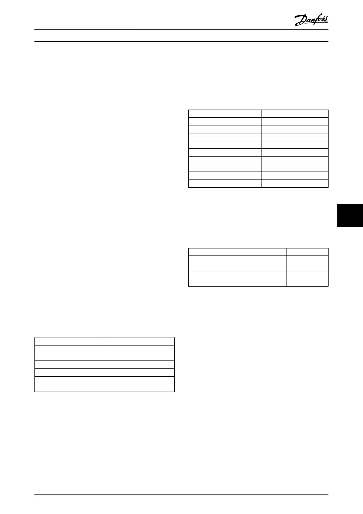
Unsigned means that there is no operational sign in the
telegram.
Data types Description
3 Integer 16
4 Integer 32
5 Unsigned 8
6 Unsigned 16
7 Unsigned 32
9 Text string
Table 8.8
8.4.12 Conversion
The various attributes of each parameter are displayed in
the section Factory Settings. Parameter values are
transferred as whole numbers only. Conversion factors are
therefore used to transfer decimals.
4-12 Motor Speed Low Limit [Hz] has a conversion factor of
0.1.
To preset the minimum frequency to 10 Hz, transfer the
value 100. A conversion factor of 0.1 means that the value
transferred is multiplied by 0.1. The value 100 is thus
perceived as 10.0.
Conversion index Conversion factor
74 0.1
2 100
1 10
0 1
-1 0.1
-2 0.01
-3 0.001
-4 0.0001
-5 0.00001
Table 8.9
8.4.13 Process Words (PCD)
The block of process words is divided into two blocks of
16 bits, which always occur in the defined sequence.
PCD 1 PCD 2
Control telegram (master⇒slave Control
word)
Reference-value
Control telegram (slave⇒master) Status word
Present output
frequency
Table 8.10
8.5 Examples
8.5.1 Writing a Parameter Value
Change 4-14 Motor Speed High Limit [Hz] to 100 Hz.
Write the data in EEPROM.
PKE=E19E Hex - Write single word in 4-14 Motor Speed High
Limit [Hz]:
IND=0000
Hex
PWEHIGH=0000 Hex
PWELOW=03E8 Hex
Data value 1000, corresponding to 100 Hz, see
8.4.12 Conversion.
RS-485 Installation and Set...
VLT
®
Micro Drive FC 51 Design Guide
MG02K202 - VLT
®
is a registered Danfoss trademark
75
8 8
Buy: www.ValinOnline.com | Phone 844-385-3099 | Email: CustomerService@valin.com

 Loading...


