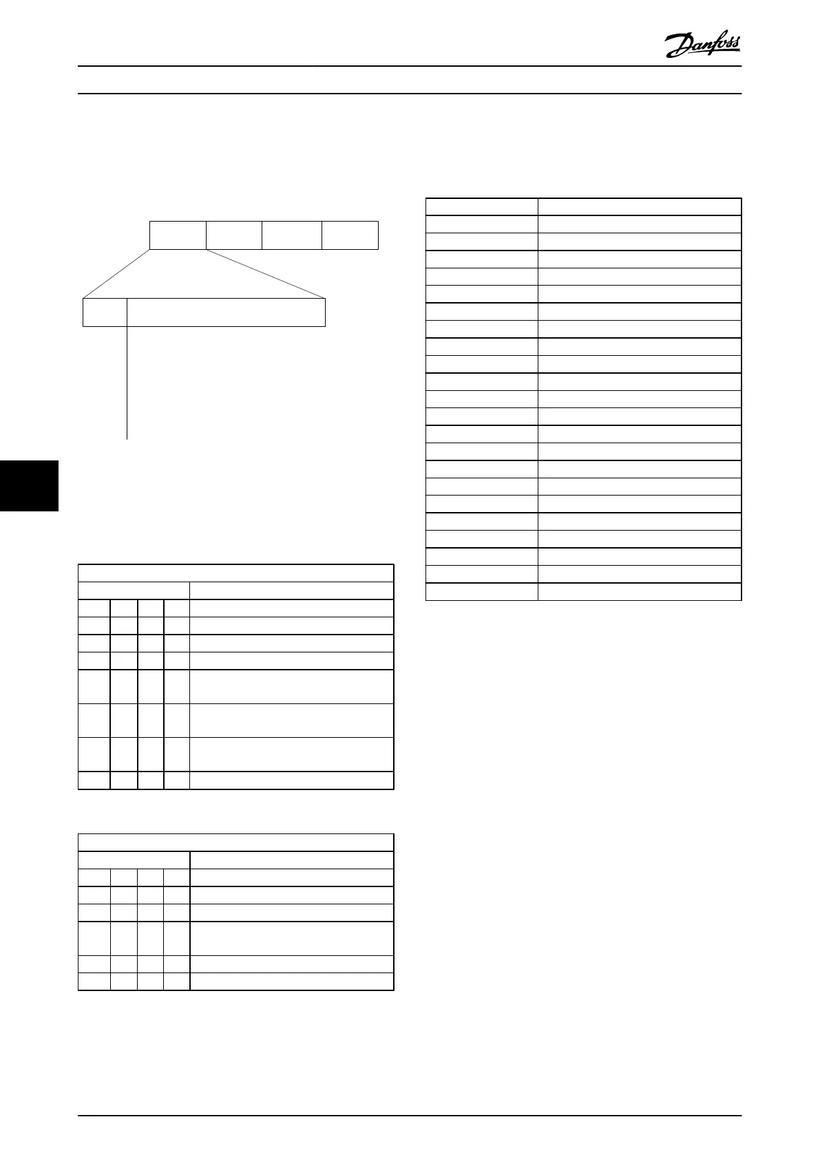
8.4.7 The PKE Field
The PKE field contains two subfields: Parameter command
and response (AK) and Parameter number (PNU):
15 14 13 12 11 10 9 8 7 6 5 4 3 2 1 0
130BB918.10
PKE IND
PWE
high
PWE
low
AK PNU
Parameter
commands
and replies
Parameter
number
Illustration 8.9
Bits no. 12-15 transfer parameter commands from master
to slave and return processed slave responses to the
master.
Parameter commands master ⇒ slave
Bit no. Parameter command
15 14 13 12
0 0 0 0 No command
0 0 0 1 Read parameter value
0 0 1 0 Write parameter value in RAM (word)
0 0 1 1 Write parameter value in RAM (double
word)
1 1 0 1 Write parameter value in RAM and
EEprom (double word)
1 1 1 0 Write parameter value in RAM and
EEprom (word)
1 1 1 1 Read text
Table 8.5
Response slave ⇒master
Bit no. Response
15 14 13 12
0 0 0 0 No response
0 0 0 1 Parameter value transferred (word)
0 0 1 0 Parameter value transferred (double
word)
0 1 1 1 Command cannot be performed
1 1 1 1 text transferred
Table 8.6
If the command cannot be performed, the slave sends this
response:
0111 Command cannot be performed
-
and issues the following fault report in the parameter
value:
Error code FC+ Specification
0 Illegal Parameter Number
1 Parameter cannot be changed.
2 Upper or lower limit exceeded
3 Subindex corrupted
4 No Array
5 Wrong Data Type
6 Not used
7 Not used
9 Description element not available
11 No parameter write access
15 No text available
17 Not while Running
18 Other error
100
>100
130 No bus access for this parameter
131 Write to factory set-up not possible
132 No LCP access
252 Unknown viewer
253 Request not supported
254 Unknown attribute
255 No error
Table 8.7
8.4.8 Parameter Number (PNU)
Bits no. 0-11 transfer parameter numbers. The function of
the relevant parameter is defined in the parameter
description in the VLT Micro Drive Programming Guide,
MG02C.
8.4.9 Index (IND)
The index is used together with the parameter number to
read/write-access parameters with an index, for example,
15-30 Alarm Log: Error Code. The index consists of 2 bytes;
a
low byte, and a high byte.
Only the low byte is used as an index.
RS-485 Installation and Set...
VLT
®
Micro Drive FC 51 Design Guide
74 MG02K202 - VLT
®
is a registered Danfoss trademark
88
Buy: www.ValinOnline.com | Phone 844-385-3099 | Email: CustomerService@valin.com

 Loading...


