EasyManuals Logo

Danfoss VLT Micro Drive FC 51 Design Guide

Danfoss VLT Micro Drive FC 51
98 pages
To Next Page IconTo Next Page
To Previous Page IconTo Previous Page
Page #57 background imageLoading...
Page #57 background image
6.12 Electrical Overview
6.12.1 Power Circuit - Overview
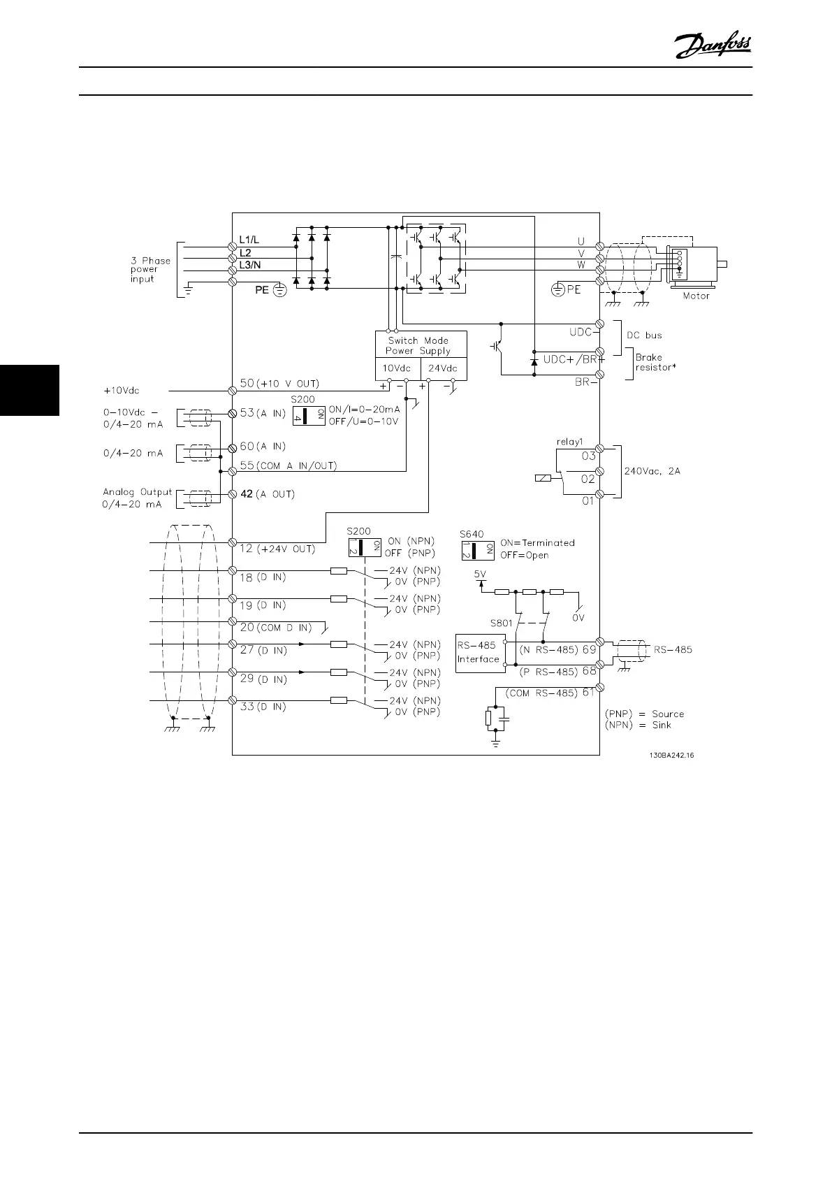
Illustration 6.12 Diagram Showing all Electrical Terminals
* Brake (BR+ and BR-) are not applicable for frame M1.
Brake resistors are available from Danfoss.
Improved power factor and EMC performance can be
achieved by installing optional Danfoss line filters.
Danfoss power filters can also be used for load sharing.
How to Install
VLT
®
Micro Drive FC 51 Design Guide
56 MG02K202 - VLT
®
is a registered Danfoss trademark
66
Buy: www.ValinOnline.com | Phone 844-385-3099 | Email: CustomerService@valin.com

Table of Contents

Other manuals for Danfoss VLT Micro Drive FC 51

Questions and Answers:

Question and Answer IconNeed help?

Do you have a question about the Danfoss VLT Micro Drive FC 51 and is the answer not in the manual?

Danfoss VLT Micro Drive FC 51 Specifications

General IconGeneral
EnclosureIP20
Output Voltage0-100% of supply voltage
AltitudeUp to 1000 m without derating
Power Range0.18-22 kW
Control MethodV/f
CommunicationModbus RTU
Protection FeaturesOver-voltage, under-voltage, over-current, over-temperature
Ambient Temperature-10°C to 50°C
Storage Temperature-25°C to 65°C
Relative Humidity5-95% (non-condensing)
Input Voltage200-240 V, 380-480 V
Braking FunctionIntegrated braking chopper (optional)

Related product manuals