between these two signals. It then adjusts the speed of the
motor
to
correct
this error.
For example, consider a pump application where the
speed of a pump is to be controlled so that the static
pressure in a pipe is constant. The desired static pressure
value is supplied to the frequency converter as the set-
point reference. A static pressure sensor measures the
actual static pressure in the pipe and supplies this to the
frequency converter as a feedback signal. If the feedback
signal is greater than the set-point reference, the
frequency converter slows down to reduce the pressure. In
a similar way, if the pipe pressure is lower than the set-
point reference, the frequency converter automatically
speed up to increase the pressure provided by the pump.
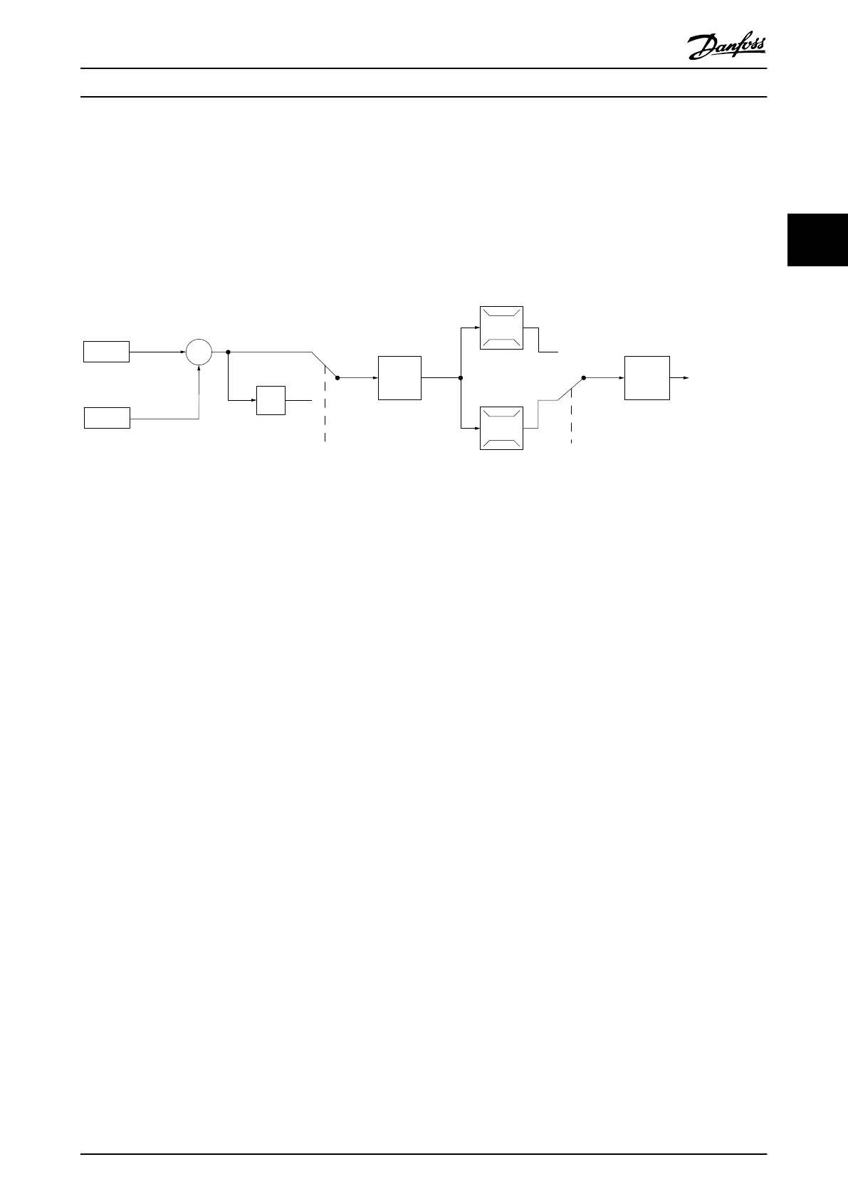
7-30 PI
Normal/Inverse
Control
PI
Reference
Feedback
Scale to
speed
P 4-10
Motor speed
direction
To motor
control
130BB894.11
S
100%
0%
-100%
100%
*[-1]
_
+
Illustration 3.3
While the default values for the frequency converter’s
Closed Loop controller often provides satisfactory
performance, the control of the system can often be
optimized by adjusting some of the Closed Loop
controller’s parameters.
Introduction to VLT® Micro ...
VLT
®
Micro Drive FC 51 Design Guide
MG02K202 - VLT
®
is a registered Danfoss trademark
19
3 3
Buy: www.ValinOnline.com | Phone 844-385-3099 | Email: CustomerService@valin.com

 Loading...


