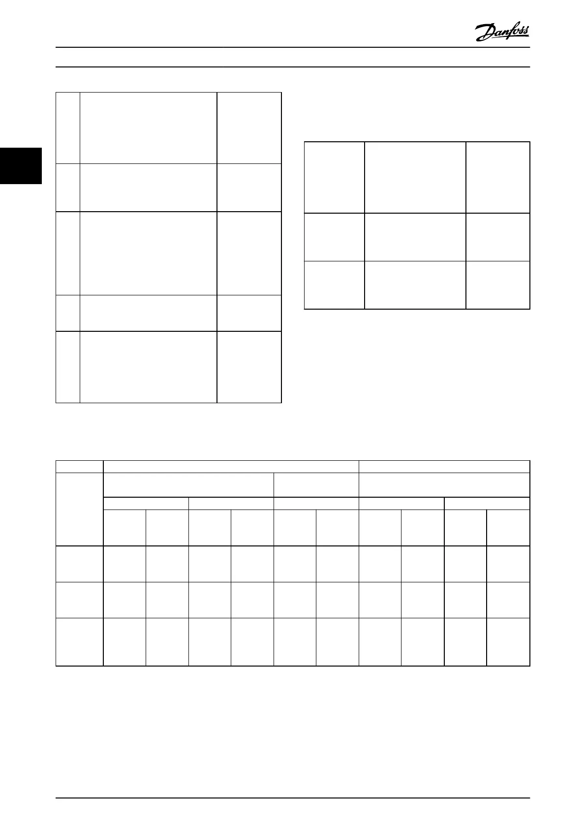
Cate-
gory
Definition
Conducted
emission
requirement
according
to
the
limits
given in EN
55011
C1 Frequency converters installed in the
first environment (home and office)
with a supply voltage less than 1000
V.
Class B
C2 Frequency converters installed in the
first environment (home and office)
with a supply voltage less than 1000
V, which are neither plug-in nor
movable and are intended to be
installed and commissioned by a
professional.
Class A Group 1
C3 Frequency converters installed in the
second environment (industrial) with a
supply voltage lower than 1000 V.
Class A Group 2
C4 Frequency converters installed in the
second environment with a supply
voltage equal to or above 1000 V or
rated current equal to or above 400 A
or intended for use in complex
systems.
No limit line.
An EMC plan
should be made.
Table 3.1 Emission Requirements
When the generic emission standards are used the
frequency
converters
are
required to comply with the
following limits
Environment Generic standard
Conducted
emission
requirement
according to the
limits given in
EN 55011
First
environment
(home and
office)
EN/IEC 61000-6-3 Emission
standard for residential,
commercial and light
industrial environments.
Class B
Second
environment
(industrial
environment)
EN/IEC 61000-6-4 Emission
standard for industrial
environments.
Class A Group 1
Table 3.2
3.2.2 EMC Test Results (Emission)
Drive type Conducted emission. Maximum shielded cable length [m] Radiated emission
Industrial environment
Housing, trades and
light
industries
Industrial environment
EN 55011 Class A2 EN 55011 Class A1 EN 55011 Class B EN 55011 Class A2 EN 55011 Class A1
Without
external
filter
With
external
filter
Without
external
filter
With
external
filter
Without
external
filter
With
external
filter
Without
external
filter
With
external
filter
Without
external
filter
With
external
filter
≤2.2 kW.
Single
phase,
230 V
25 - 15 50 5 15 Yes - No Yes
≤7.5 kW. Up
to 500 VAC,
three phase
25 - 15 50 - 15 Yes - No Yes
11 kW to 22
kW. Up to
500 VAC,
three phase
25 - 15 50 - 15 Yes - No Yes
Table 3.3 EMC Test Result
Introduction to VLT® Micro ...
VLT
®
Micro Drive FC 51 Design Guide
22 MG02K202 - VLT
®
is a registered Danfoss trademark
33
Buy: www.ValinOnline.com | Phone 844-385-3099 | Email: CustomerService@valin.com

 Loading...


