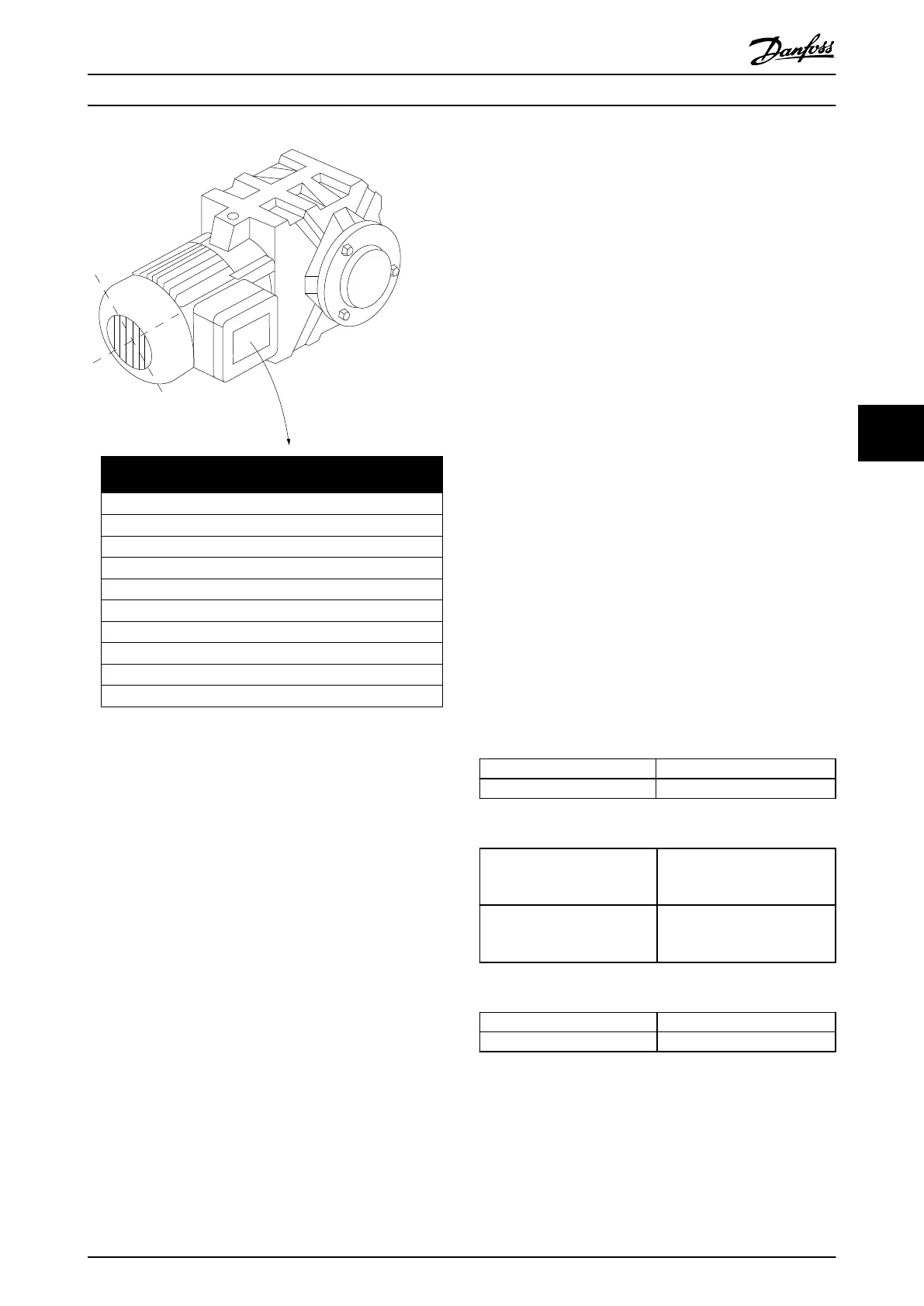
3~ MOTOR NR. 1827421 2003
S/E005A9
1,5 KW
n 31,5 /min. 400 Y V
n 1400 /min. 50 Hz
COS 0,80 3,6 A
1,7L
B IP 65 H1/1A
BAUER D-7 3734 ESLINGEN
130BT307.10
Illustration 6.17
Step 3. Activate the Automatic Motor Tuning (AMT)
Performing an AMT ensures optimum performance. The
AMT measures the values from the motor model
equivalent diagram.
1. Connect terminal 27 to terminal 12 or set
5-12 Terminal 27 Digital Input to 'No function'
(5-12 Terminal 27 Digital Input
[0])
2.
Activate the AMT 1-29 Automatic Motor
Adaptation (AMA).
3. Choose between complete or reduced AMT. If an
LC filter is mounted, run only the reduced AMT,
or remove the LC filter during the AMT
procedure.
4. Press [Ok]. The display shows “Press [Hand On] to
start”.
5. Press [Hand On]. A progress bar indicates if the
AMT is in progress.
Stop the AMT during operation
1.
Press [Off] - the frequency converter enters into
alarm mode and the display shows that the AMT
was terminated by the user.
Successful AMT
1. The display shows “Press [Ok] to finish AMT”.
2. Press the [Ok] key to exit the AMT state.
Unsuccessful AMT
1. The frequency converter enters into alarm mode.
A description of the alarm can be found in the
Troubleshooting section in VLT Micro Drive FC 51
Programming Guide, MG02C.
2.
"Report Value” in the [Alarm Log] shows the last
measuring sequence carried out by the AMT,
before the frequency converter entered alarm
mode. This number along with the description of
the alarm assists in troubleshooting. Contact
Danfoss Service and make sure to mention
number and alarm description.
Unsuccessful AMT is often caused by incorrectly registered
motor name plate data or too big difference between the
motor power size and the frequency converter power size.
Step 4. Set speed limit and ramp time
Set-up the desired limits for speed and ramp time.
Minimum Reference
3-02 Minimum Reference
Maximum Reference
3-03 Maximum Reference
Table 6.7
Motor Speed Low Limit
4-11 Motor Speed Low Limit
[RPM]
or 4-12 Motor Speed Low
Limit [Hz]
Motor Speed High Limit
4-13 Motor Speed High Limit
[RPM] or 4-14 Motor Speed High
Limit [Hz]
Table 6.8
Ramp-up Time 1 [s]
3-41 Ramp 1 Ramp Up Time
Ramp-down Time 1 [s]
3-42 Ramp 1 Ramp Down Time
Table 6.9
How to Install
VLT
®
Micro Drive FC 51 Design Guide
MG02K202 - VLT
®
is a registered Danfoss trademark
59
6 6
Buy: www.ValinOnline.com | Phone 844-385-3099 | Email: CustomerService@valin.com

 Loading...


