CP80 and CP80 Plus Service Manual 2-35
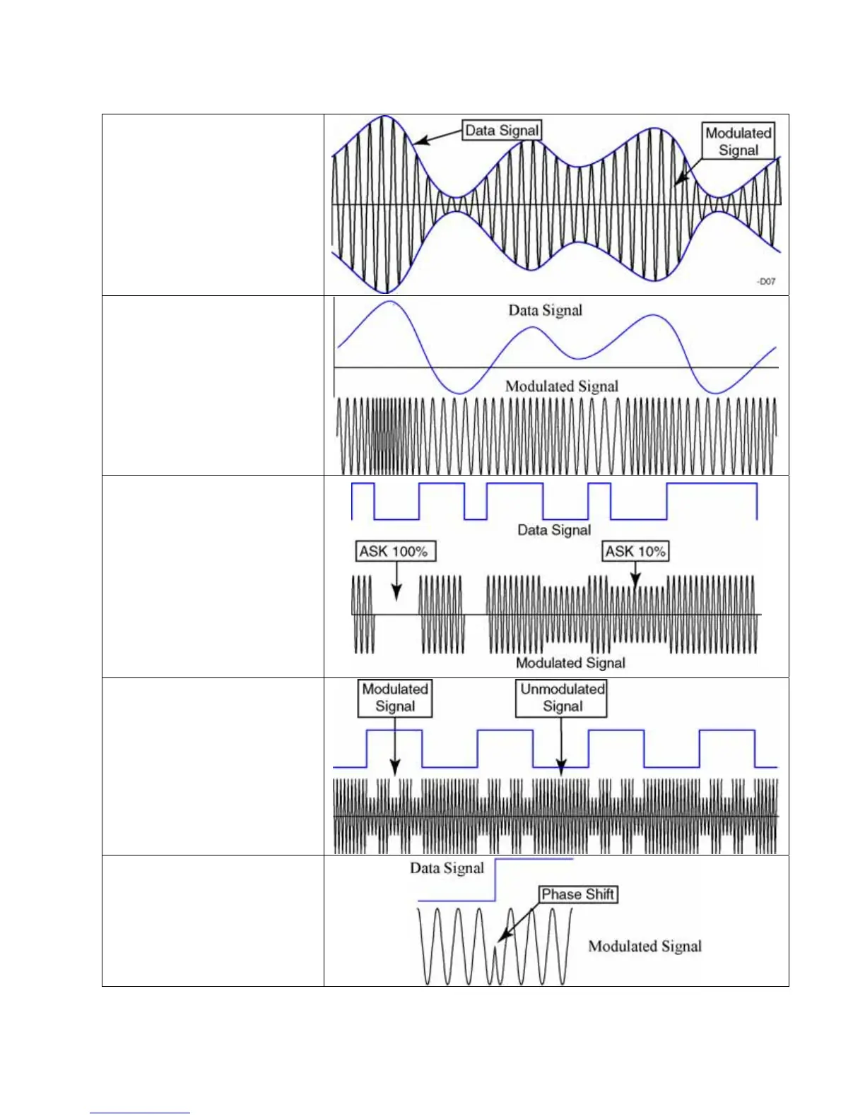
Signal Modulation Summary Diagram
Amplitude Modulation:
The magnitude (height) of the
carrier signal is varied according
to the height of the data signal.
This is what is used in AM radio.
Note: The blue data signal is
shown here for clarity. It is not
actually present in the actual
modulated signal.
Frequency Modulation:
The frequency of the carrier
signal is varied according to the
height of the data signal. This is
what is used in FM radio.
Note: The modulated frequency
remains close to the carrier
frequency, but the drawing is
exaggerated for clarity.
Amplitude Shift Keying:
This is a digital variant on the
AM modulation. It comes in two
common forms: 100% and 10%.
Note: 10% modulation
(ASK10%) means the carrier is
modulated by only 10%. 100%
modulation means that the
carrier signal is fully modulated.
Both of these variants are shown
to the right.
Load Modulation:
The card switches the resistance
of its antenna, which alters the
current in the transmitter.
Note: This is a complex topic
and will be discussed in greater
detail later.
Phase Modulation:
A data transition is signified by
a shift in the signal’s phase. In
this case, the phase is shifted 180
degrees by inverting the signal.