TC1200 REFERENCE MANUAL
4
2
2.1.2 Electrical Connections
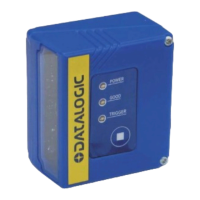
The TC1200-1000 Scanner is equipped with a 9-pin Male D-Sub connector for connection to
the power supply and input/output signals. The details of the connector pins are indicated in
the following table:
Figure 2 - 9-pin Male D-sub Connector
9-pin Connector
1 VCC +5Vdc
2 GND Ground
3 RX Receive Data
4 TX Transmit Data
5 OUT1 + Output signal 1, positive
6 OUT1/2 - Output signal 1/2, negative
7 OUT2 + Output signal 2, positive
8 EXT-TRIG + External Trigger Input, positive
9 EXT-TRIG - External Trigger Input, negative
Table 1 - TC1200-1000 Scanner Pinout
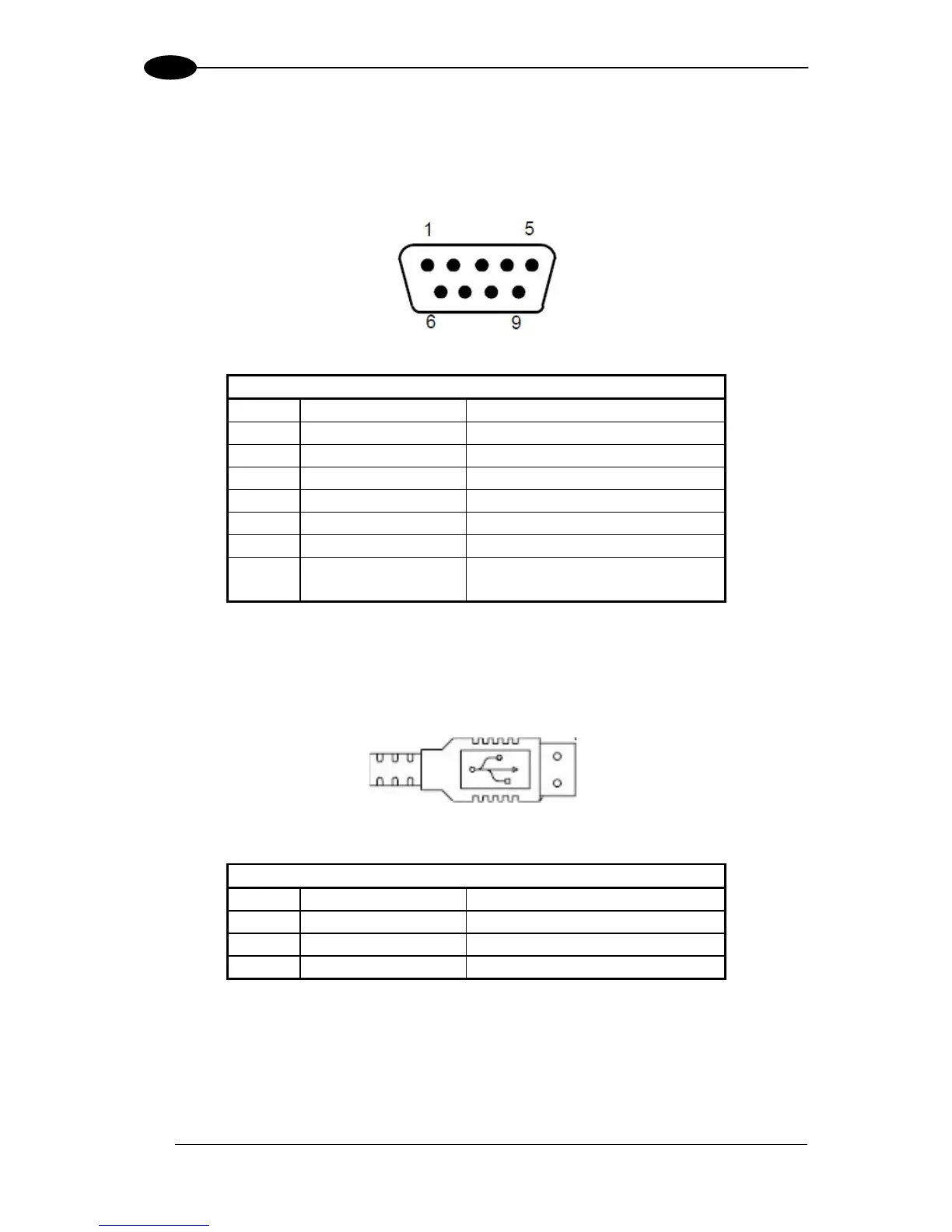
The TC1200-1100 Scanner is equipped with a USB Type A connector for connection to the
PC standard USB Port. The details of the connector pins are indicated in the following table:
Figure 3 – USB Type A Connector
USB Type A Connector
1 VCC +5 Vdc
2 DATA - USB Data, negative
3 DATA + USB Data, positive
4 GND Ground
Table 2 - TC1200-1100 Scanner Pinout
 Loading...