INSTALLATION
9
2
2.2.2 Electrical Connections
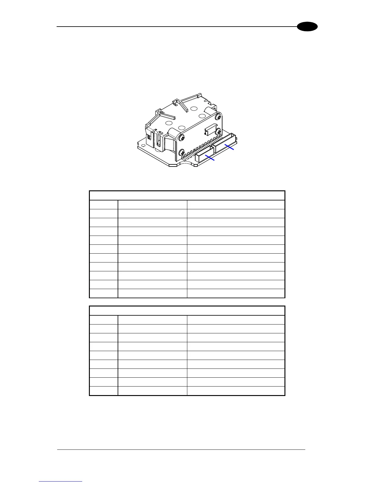
The TC1200-0X00 Scan Engine is equipped with an 8-pin and a 10-pin DF13 connector for
connection to the power supply and input/output signals. The details of the connector pins
are indicated in the following table:
Figure 5 – 10 and 8-pin Connectors
J1
Pin Signal Description
1 D- USB Data negative
2 D+ USB Data positive
3 GND power ground
4 GND power ground
5 TX transmit data
6 RTS NOT USED
7 RX receive data
8 CTS NOT USED
9 VCC +5Vdc
10 GND power ground
J2
Pin Signal Description
1 GND power ground
2 NC
3 OUT2+ Output 2 positive
4 OUT1/2- Output 1/2 negative
5 OUT1+ Output 1 positive
6 NC
7 EXT TRIG- External Trigger Input positive
8 EXT TRIG+ External Trigger Input negative
Table 3 - TC1200 Scan Engine Pinout
J1
J2
 Loading...