Steps
1. Connect the coin-cell battery cable to its connector on the system board and flip the system board.
2. Replace the seven (M2x5) screws to secure the system board to the computer chassis.
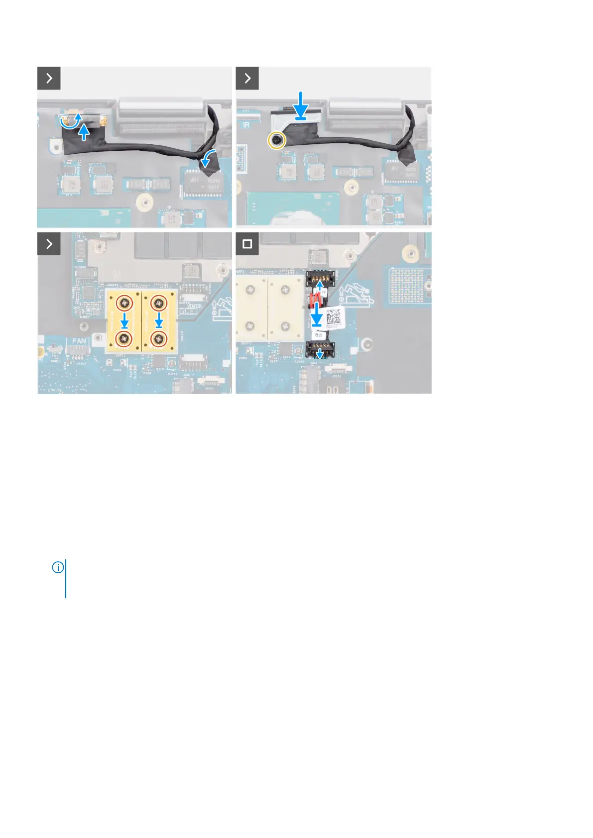
3. Replace the display cable bracket on the display cable.
4. Replace the (M2x5) screw to secure the display cable bracket to the system board.
5. Connect the power button board FFC from the system board, touchpad FFC, USH daughter board FFC (for models shipped
with a USH daughter board), and SD card reader FPC cables.
6. Connect the display cable to its connector on the system board.
7. Replace the (M2x5) screw to secure the display cable bracket in place.
8. Align the screw holes, and replace the four (M2x6) screws to secure the two PCB beam connectors to the system board
and the GPU card.
NOTE:
For models shipped with an integrated GPU card, the PCB beam connectors are on the bottom and top-right
side of the GPU card. For models shipped with a discrete GPU card, the PCB beam connectors are at the bottom side of
the GPU card.
9. Connect the GPU power cable to the connector on the system board on the top side of the computer.
10. Lock the GPU power cable connector on the system board.
Next steps
1. Install the inner frame.
2. Install the heat-sink for integrated graphics or heat-sink for discrete graphics.
3. Install the secondary solid-state drive.
4. Install the primary solid-state drive.
5. Install the WWAN card.
6. Install the WLAN card.
7. Install the interposer board module.
8. Install the CAMM module or long CAMM module or memory module.
Removing and installing components
71