Chapter 12 Positioning Module AS02/04PU
12 - 5
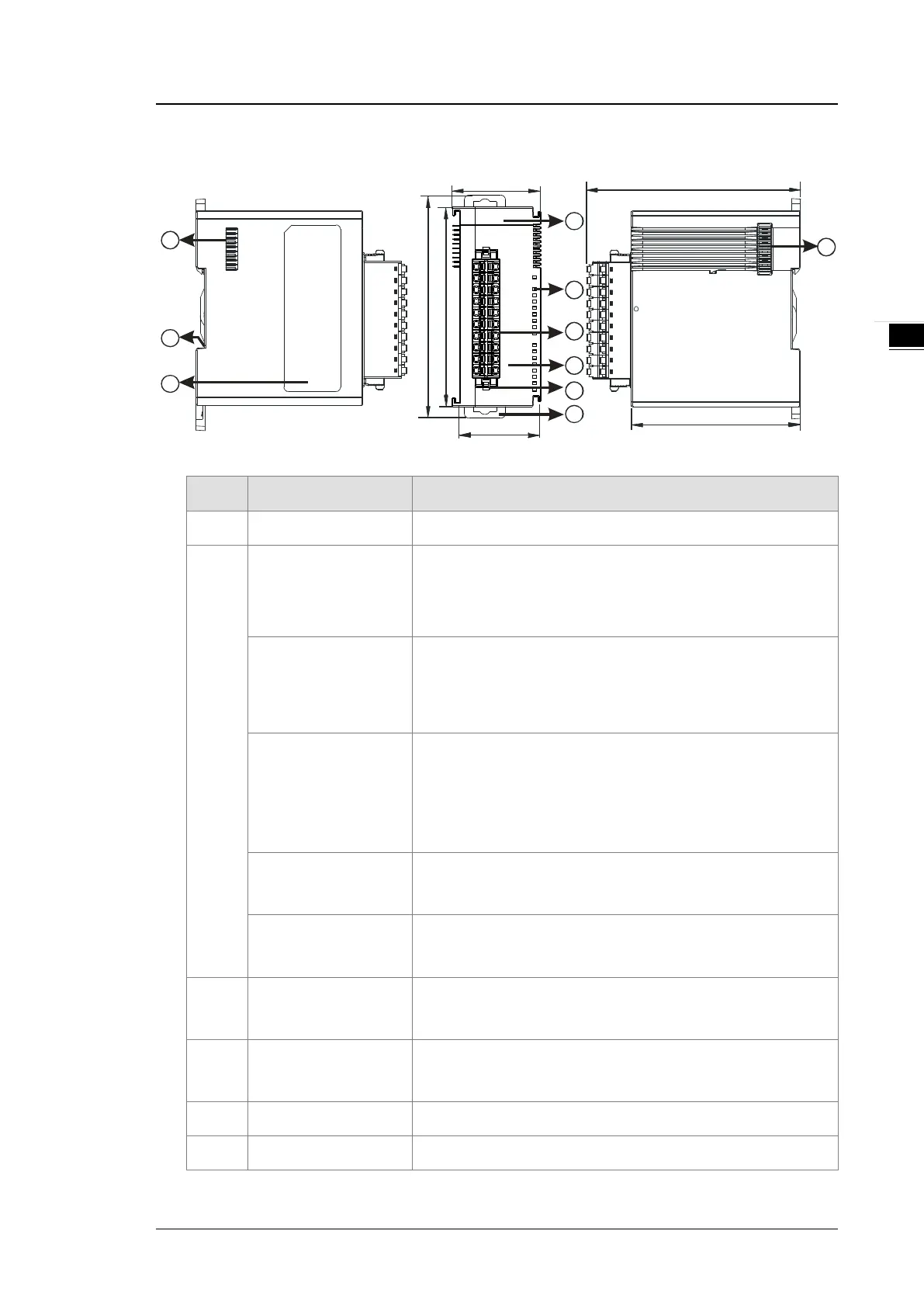
12.2.2. Profile
2
38.2 95
75
35
88
98 .3
1
4
5
2
3
6
7
7
8
9
Unit: mm
Number
Name Description
1 Model name Model name of the module
2
POWER LED indicator
(Blue)
Indicates the status of the power supply
ON: the power is on
OFF: no power
Run LED indicator
(Green)
Operating status of the module
ON: the module is running and ready to accept instructions.
OFF: the module is stopped and can NOT accept instrucitons.
Error LED indicator
(Red)
Error status of the module
OFF: the module is normal.
Blinking (0.2 seconds ON/OFF): hardware error occurs in the
module, can NOT operate normally
Input LED indicator
(Red)
ON: Receives an input signal
OFF: Receives no input signal
Output LED indicator
(Red)
ON: Receives an output signal
OFF: Receives no output signal
3
Removable terminal
block
The inputs are connected to sensors.
The outputs are connected to loads to be driven.
4
Arrangement of the
input/output terminals
Arrangement of the terminals
5 Terminal block clip Removal of the terminal block
6 DIN rail clip Secures the module onto the DIN rail
 Loading...
