Chapter 12 Positioning Module AS02/04PU
12 - 21
12.4 Troubleshooting
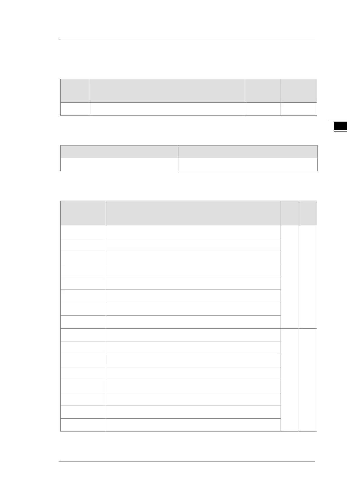
12.4.1. Error Codes
Error
Code
Description
A
D LED
indicator
ERROR LED
indicator
16#1802
Hardware failure OFF
Blinking
12.4.2. Troubleshooting Procedure
Description Procedure
Hardware failure Return the module to the factory for repair.
12.4.3. State Codes (Axis 1 - 4)
State Code
Byte #
Description
Axis
1-2
Axis
3-4
0 Error flag
1 Axis 3
1 The output is active.
2 The output has stopped working.
3 The instruction execution is complete.
4 Pulse in positive direction not allowed
5 Pulse in negative direction not allowed
6 Current position value overflow
7 Pulse direction (positive or negative)
8 Error flag
Axis 2
Axis 4
9 The output is active.
10 The output has stopped working.
11 The instruction execution is complete.
12 Pulse in positive direction not allowed
13 Pulse in negative direction not allowed
14 Current position value overflow
15 Pulse direction (positive or negative)
 Loading...
