AS Series Module Manual
11-74
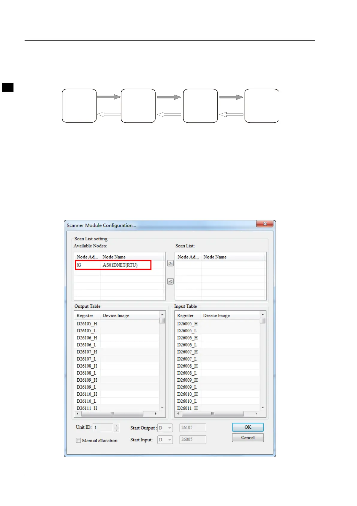
11.5.4.3. DeviceNet Mapping Data
The model of the entire mapping data exchange is displayed below and eventually data will map to the registers in the
PLC of the master.
Note: All mapping addresses mentioned below means the D registers in the PLC.
The start input address and start output address of AS01DNET (RTU) are assigned automatically by the master when
AS01DNET (RTU) is added to the master. The input mapping address length and output mapping address length of
AS01DNET (RTU) are determined by the configuration of modules connected to AS01DNET (RTU).
The start input and output mapping addresses of one I/O module are assigned automatically by the software. Its input
mapping address length and output mapping address length are determined by the configuration of the module. The range
of input / output mapping address is limited by the input / output mapping address range of AS01DNET (RTU).
11.5.4.3.1. The Rule for Assignment of Mapping Addresses by AS01DNET Master
PLC
DeviceNET IO modules
AS 01DNET
AS0 1DNE T
(RTU)
 Loading...
