Chapter 4 Analog Output Module AS04DA
4- 5
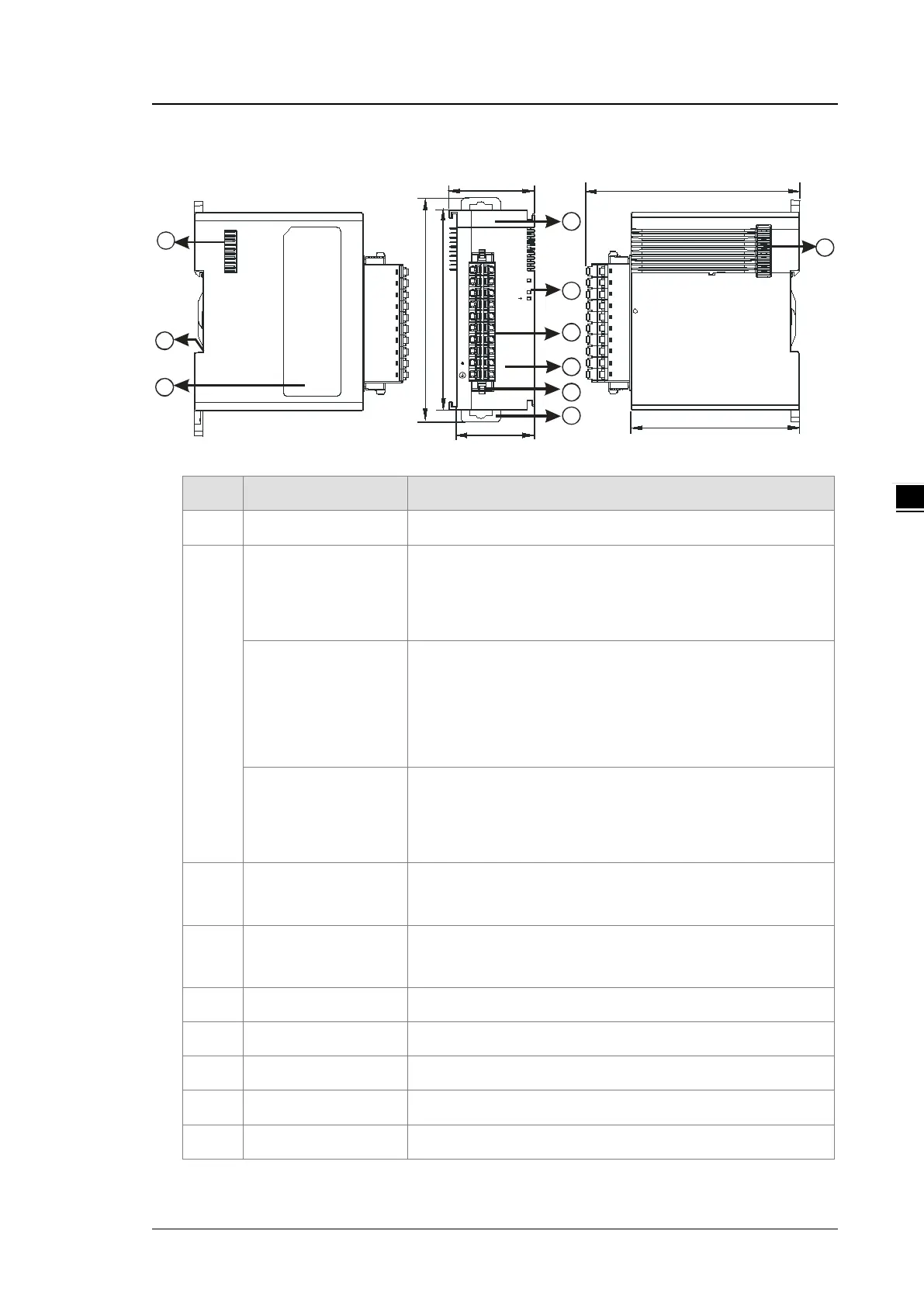
4.2.2 Profile
38.2
35
88
98.3
1
4
5
2
3
6
D A
VO1
VO2
AG
SLD
AG
VO4
0V
24V
SLD
SLD
AG
IO3
AG
SLD
IO1
IO4
IO2
04DA
PWR
ERR
VO3
7
8
9
95
75
7
unit: mm
Number
Name Description
1 Model Name Model name of the module
2
POWER LED Indicator
Status of the power supply
ON: the power is on.
OFF: the power is off.
ERROR LED Indicator
Error status of the module
ON: a serious error exists in the module.
OFF: the module is operating normally.
Blinking: a minor error exists in the module.
Digital-to-Analog
conversion Indicator
Digital-to-Analog conversion status
Blinking: conversion is in process.
OFF: conversion has stopped.
3
Removable Terminal
Block
Outputs are connected to loads to be driven.
4
Arrangement of the
Input/Output Terminals
Arrangement of the terminals
5 Terminal Block Clip For removing the terminal block
6 DIN Rail Clip Secures the module onto the DIN rail
7 Module Connecting Set Connects the modules
8 Ground Clip
9 Label Nameplate
 Loading...
