EasyManuals Logo

Delta AS Series Manual

Delta AS Series
632 pages
To Next Page IconTo Next Page
To Previous Page IconTo Previous Page
Page #66 background imageLoading...
Page #66 background image
AS Series Module Manual
3- 22
_3
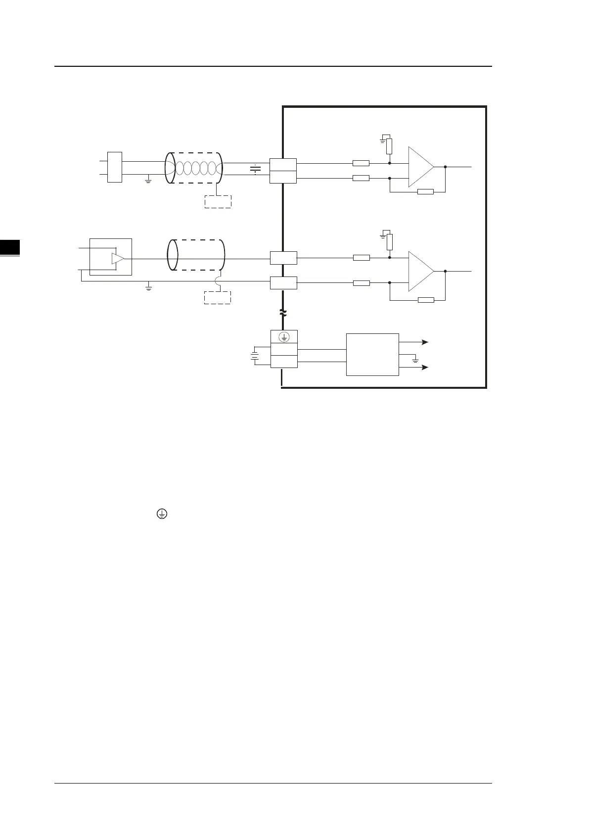
AS08AD-B External wiring
4 w ire vo lt ag e inp u t-
-10 V~ + 10 V
V 1+
V1 -
C H X
1 M
A G
1 M
0V
2 4V
2 4 VD C
D C / DC
C on ve rte r
+ 1 5V
-1 5V
AG
FE
*3
*4
+
-
V2 +
V 2-
1M
A G
1 M
+ 2 4V
0V
-1 0 V~ + 10 V
+ 2 4V
+
-
* 3
FE
0 V
*5
CH X
*5
3 wire v olt ag e in pu t-
*2
Sh ield ed c ab le 1*
S hie ld ed ca b le 1*
*1. Use shielded cables to isolate the analog input signal cable from other power cables.
*2. If variability in the input voltage results in interference within the wiring, connect the module to a capacitor
with a capacitance between 0.10.47 μF and a working voltage of 25 V.
*3. Connect the shielded cable to the terminal FE.
*4. Connect the terminal to the ground terminal.
*5. Every channel can operate with the wiring presented above.

Table of Contents

Other manuals for Delta AS Series

Questions and Answers:

Question and Answer IconNeed help?

Do you have a question about the Delta AS Series and is the answer not in the manual?

Delta AS Series Specifications

General IconGeneral
SeriesAS Series
Power Supply24VDC
Cooling MethodNatural convection
Programming LanguageFunction Block Diagram (FBD)
Communication InterfaceEthernet, RS-232, RS-485
Output Voltage24V DC
Output Current2A
Operating Temperature55°C
Storage Temperature70°C
Protection FeaturesOvervoltage
CertificationsCE, UL

Related product manuals