Chapter 4 Analog Output Module AS04DA
4- 7
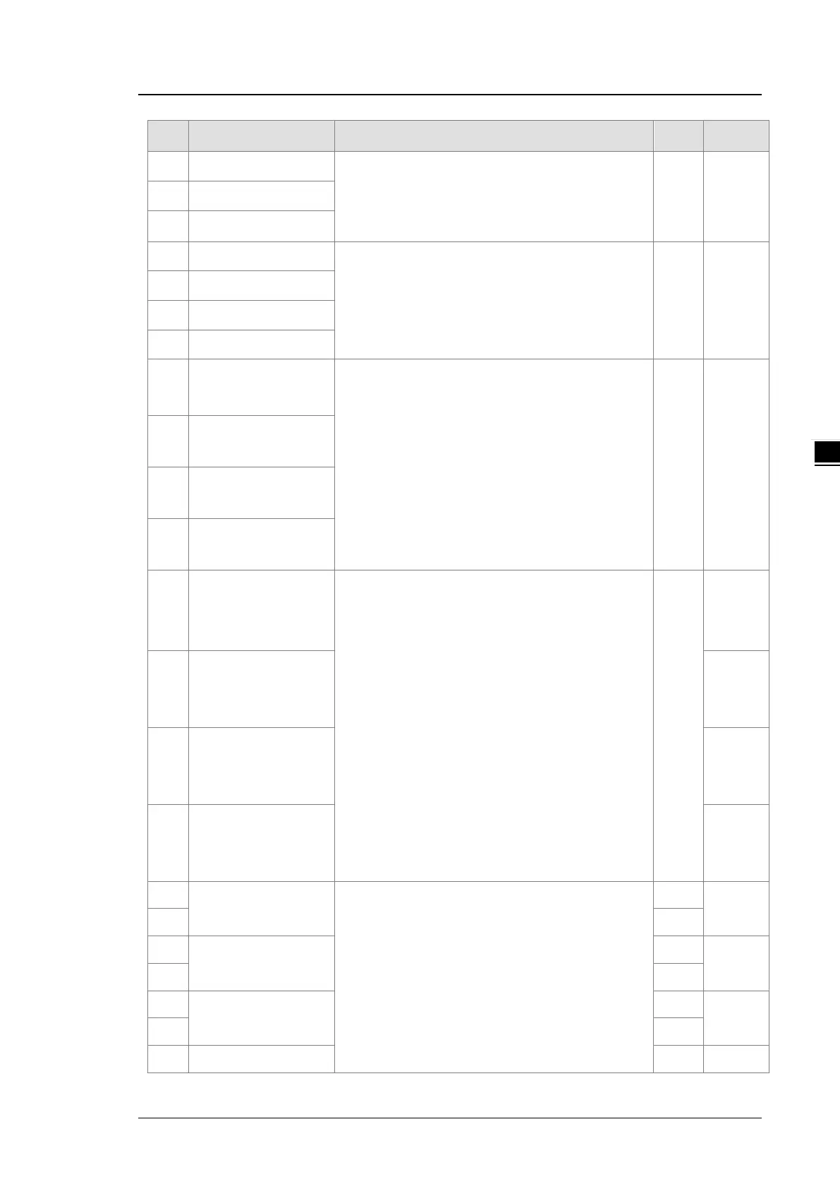
CR# Name Description
Atr. Defaults
6
Channel 2 offset
7
Channel 3 offset
8
Channel 4 offset
9
Channel 1 gain
Range: -32768 to +32767
R/W 1000
10
Channel 2 gain
11
Channel 3 gain
12
Channel 4 gain
13
sent by channel 1
0: when the PLC stops, the value of the analog output
is reset to 0.
1: when the PLC stops, the value of the analog output
is retained.
R/W 0
14
sent by channel 2
15
sent by channel 3
16
sent by channel 4
17
Refreshing the time for
an output
channel 1
Range: 10–3200 (100 ms–32000 ms)
Unit: 10 ms
Any value less than 10 is processed as 0. Any value
larger than 3200 is processed as 3200.
Set the value to 0 to disable this function.
R/W
0
18
Refreshing the time for
channel 2
0
19
Refreshing the time for
channel 3
0
20
Refreshing the time for
channel 4
0
21
range for channel 1
When the format is set to integer in HWCONFIG, the
scale range is invalid.
For analog-digital modules, it is much more convenient
if the system can convert digital values to floating-point
values for earier understanding. Here you can set the
minimum and maximum scale ranges of corresponding
floating-point values for channels.
R
-10.0
22 R
23
range for channel 2
R
-10.0
24 R
25
The m
range for channel 3
R
-10.0
26 R
27
The m
R -10.0
 Loading...
