Chapter 4 Analog Output Module AS04DA
4- 13
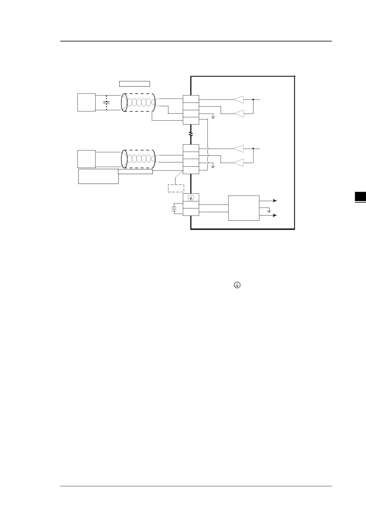
External wiring
C on ve rte r
VO4
IO4
AG
CHX
0mA~20mA
CH4
AG
VO1
IO1
AG
CHX
-10V~+10V
*2
CH1
AG
24VDC
DC/DC
+15V
-15V
AG
SLD
SLD
FE
*3
0V
24V
*4
*4
AC m otor driv e,
recorder,
proportioning v alv e
AC motor driv e,
recorder,
proporti oni ng v alve
*1. Use shielded cables to isolate the analog input signal cable from other power cables.
*2. If variability in the input voltage results in interference within the wiring, connect the module to a capacitor
having a capacitance between 0.1–0.47 μF and a working voltage of 25 V.
*3. Connect the SLD to FE, and connect both the FE and the terminal to the ground terminal.
*4. Every channel can operate with the wiring presented above.
 Loading...
