Chapter 1 CoE Drive Overview ASDA A2-E
Revision April, 2015 1-7
1.5 Wiring
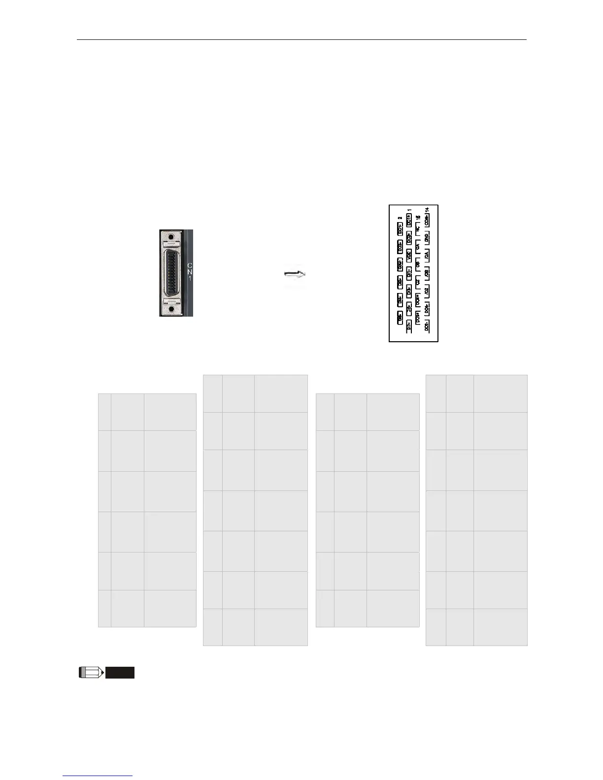
I/O Signal (CN1) Connection and Connector Terminal Layout
In order to have a more flexible communication with the master, 4 programmable
Digital Output (DO) and 7 programmable Digital Input (DI) are provided, which are
parameter P2-18~P2-21 and P2-10~P2-16 respectively. In addition, the differential
output encoder signal A+, A-, B+, B-, Z+ and Z- is also provided. The followings are
the pin diagrams.
CN1 Connector (female)
CN1 Connector (male)
rear view
1 DO1+
Digital
output
14 COM-
VDD power
ground
2 DO1-
Digital
output
15 NC N/A
3 DO2+
Digital
output
16 GND
Analog
input signal
ground
4 DO2-
Digital
output
17 OA
Encoder/
A pulse
output
5 VDD
+24V Power
output
18 /OA
Encoder/
A pulse
output
6 COM+
Power input
(12~24V)
19 OB
Encoder/
B pulse
output
7 DI1- Digital input
20 /OB
Encoder/
B pulse
output
8 DI2- Digital input
21 OZ
Encoder/
Z pulse
output
9 DI3- Digital input
22 /OZ
Encoder/
Z pulse
output
10 DI4- Digital input
23 DO4+
Digital
output
11 DI5- Digital input
24 DO4-
Digital
output
12 DI6- Digital input
25 DO3+
Digital
output
13 DI7- Digital input
26 DO3-
Digital
output
NOTE
NC means NO CONNECTION. This terminal is for internal use only. Do not connect it, or it may damage the
servo drive.