Chapter 1 CoE Drive Overview ASDA A2-E
Revision April, 2015 1-13
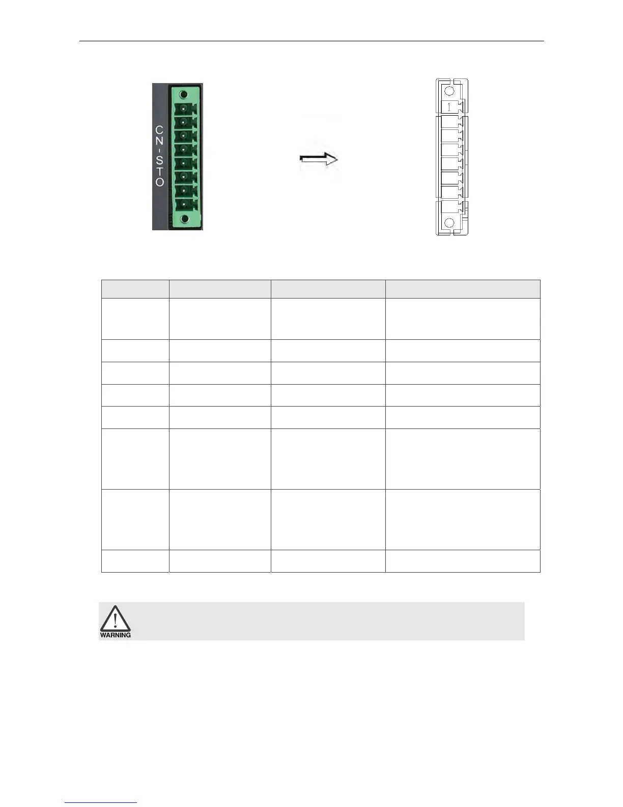
1.5.6 CN-STO
CN-STO Connector (male)
Pin No Signal Name Terminal Symbol Function and Description
*1
VDD24V
power
COM+
VDD (24V) power is the same
as the voltage of Pin11 in CN1
2 STO_A STO_A STO input pin A+
3 /STO_A /STO_A STO input pin A-
4 STO_B STO_B STO input pin B+
5 /STO_B /STO_B STO input pin B-
6 FDBK_A FDBK_A
STO alarm output pin A,
Relay Output
Max. Current : 1A
7 FDBK_B FDBK_B
STO alarm output pin B,
Relay Output
Max. Current : 1A
8 COM- COM- VDD(24V) power ground
Caution: Do not apply to dual power or it may damage the servo drive.