ASDA A2-E Chapter 1 Coe Drive Overview
1-8 Revision April, 2015
1.5.1 Explanation of I/O (CN1) Connector Signal
The following details the signals listed in previous section.
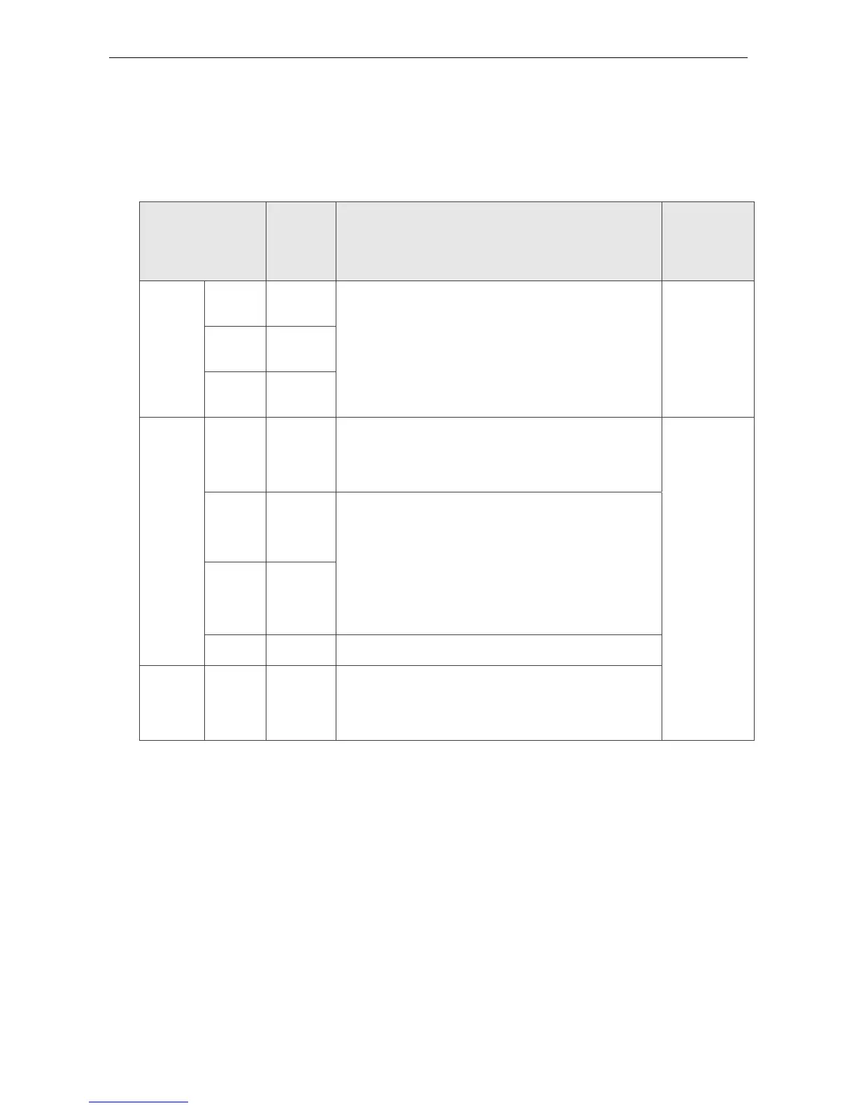
General Signals
Signal Name Pin No Function
Wiring
Method
(Refer to
3.4.3)
Position
pulse
(output)
OA
/OA
17
18
Encoder signal output A, B, Z (Line Driver output)
C13/C14
OB
/OB
19
20
OZ
/OZ
21
22
Power
VDD 5
VDD is the +24V power provided by the drive and
is for Digital Input (DI) and Digital Output (DO)
signal. The maximum current is 500mA.
-
COM+ 6
COM+ is the common input of Digital Input (DI)
and Digital Output (DO) voltage. When using
VDD, VDD should be connected to COM+. If not
using, it needs to apply the external power (+12V
~+24V). Its positive end should connect to COM+
and the negative end should connect to COM-.
COM- 14
GND 16
VCC voltage is based on GND.
Other NC 15
NO CONNECTION. This terminal is for internal
use only. Do not connect it, or it may damage the
servo drive.